Download
1 / 24
481 likes | 1.19k Vues
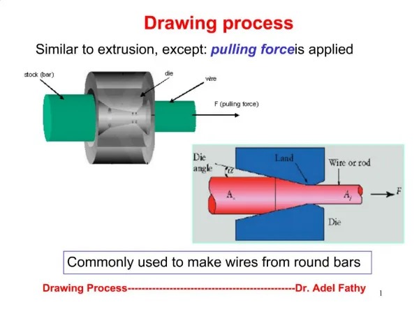
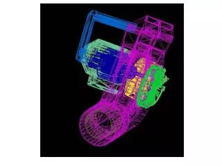
Drawing Process. Drawing is a metalworking process which uses tensile forces to stretch metal. It is broken up into two types: sheet metal drawing and wire, bar, and tube drawing.

E N D
Drawing is a metalworking process which uses tensile forces to stretch metal. • It is broken up into two types: sheet metal drawing and wire, bar, and tube drawing. • For wire, bar, and tube drawing the starting stock is drawn through a die to reduce its diameter and increase its length. • Drawing is usually done at room temperature, thus classified a cold working process, however it may be performed at elevated temperatures to hot work large wires, rods or hollow sections in order to reduce forces
Drawing operations involve pulling metal through a die by means of a tensile force applied to the exit side of the die. • The plastic flow is caused by compression force, arising from the reaction of the metal with the die. • Starting materials: hot rolled stock (ferrous) and extruded (nonferrous). • Material should have high ductility and good tensile strength. • Bar, wire and tube drawing are usually carried out at room temperature, except for large deformation, which leads to considerable rise in temperature during drawing. • The metal usually has a circular symmetry (but not always, depending on requirements).
Wire drawing • Wire drawing involves reducing the diameter of a rod or wire by passing through a series of drawing dies or plates. • The subsequent drawing die must have smaller bore diameter than the previous drawing die
Tube drawing • Tube drawing involves reducing the cross section and wall thickness through a draw die • The cross section can be circular, square hexagonal or in any shapes
Wire drawing die • Shape of the bell causes hydrostatic pressure to increase and promotes the flow of lubricant into the die. • The approach angle – where the actual reduction in diameter occurs, giving the half die angle α. • The bearing region produces a frictional drag on the wire and also remove surface damage due to die wear, without changing dimensions. • The back relief allows the metal to expand slightly as the wire leaves the die and also minimises abrasion if the drawing stops or the die is out of alignment. • The die nib made from cemented carbide or diamond is encased for protection in a thick steel casing
Drawing die materials • Most drawing dies are cemented carbide or industrial diamond (for fine wires). • Cemented carbides are the most widely used for drawing dies due to their superior strength, toughness, and wear resistance. • Cemented carbide is composed of carbides of Ti, W, Ni, Mo, Ta, Hf. • Polycrystalline Diamond (PCD) used for wire drawing dies – for fine wires. Longer die life, high resistance to wear, cracking or bearing.
Wire drawing process • Bull block drawing allows the generation of long lengths • Area reduction per drawing pass is rarely greater than 30-35%.
Stepped-cone multiple-pass wiredrawing • More economical design. • Use a single electrical motor to drive a series of stepped cones. • The diameter of each cone is designed to produce a peripheral speed equivalent to a certain size reduction.
Analysis of wiredrawing • From the uniform-deformation energy method, a draw stress is given by Eq. 1
Consider the problem of strip drawing of a wide sheet A wide strip is being drawn through a frictionless die with a total included angle of 2α Plane strain condition is applied (no strain in the width direction.) The equilibrium of forces in the x direction is made up of two components 1. Due to the change in longitudinal stress with x increasing positively to the left. 2. Due to the die pressure at the two interfaces. Taking equilibrium of force in the x direction and neglecting dσx dh Eq.2
We shall now consider the problem of strip drawing where a Coulomb friction coefficient exists between the strip and the die. The equilibrium now includes 2µpdx Taking equilibrium of forces in the x direction eq.2 becomes Since h = 2x tan α, and dh = 2dx tanα, then 2dx = dh/tan α We now have Eq. 3
Since the yield condition for plane strain is σx + p = σ’0 and B = µ cot α, the differential equation for strip drawing is Eq. 4 If B and σ’0 are both constant, Eq.4 can be integrated directly to give the draw stress σxa For wire drawing conducted with conical dies, Eq. 5
Analysis for wiredrawing with friction The surface area of contact between the wire and the die is given by Eq. 6 • p is the mean normal pressure on this area. • Pd is the draw force Balancing the horizontal components of the frictional force and the normal pressure. Eq. 7
In the asence of friction, B = 0 and Eq. 8 The draw stress with friction is given by Eq. 9
If redundant work is included in Eq. 9, the expression becomes Eq. 10 Where Ф is a factor for the influence of redundant work, which can be defined as Eq. 11 Where ε* = the enhanced strain corresponding to the yield stress of the metal, which has been homogeneously deformed to a strain ε
Tube drawing processes • Following the hot forming process, tubes are cold drawn using dies, plugs or mandrels to the required shape, size, tolerances and mechanical strength. • provides good surface finishes. • increase mechanical properties by strain hardening. • can produce tubes with thinner walls or smaller diameters than can be obtained from other hot forming methods. • can produce more irregular shapes.
Classification of tube drawing processes There are three basic types of tube-drawing processes 1. Sinking 2. Plug drawing - Fixed plug - Floating plug 3. Mandrel drawing
Tube sinking • The tube, while passing through the die, shrinks in outer radius from the original radius R0to a final radius R0f • No internal tooling (internal wall is not supported), the wall then thicken slightly. • Uneven internal surface. • The final thickness of the tube depends on original diameter of the tube, the die diameter and friction between tube and die. • Lower limiting deformation.
Fixed plug drawing • Use cylindrical / conical plug to control size/shape of inside diameter. • Use higher drawing loads than floating plug drawing. • Greater dimensional accuracy than tube sinking. • Increased friction from the plug limit the reduction in area (> 30%). • can draw and coil long lengths of tubing.
Floating plug drawing • A tapered plug is placed inside the tube. • As the tube is drawn the plug and the die act together to reduce both the outside/inside diameters of the tube. • Improved reduction in area than tube sinking (~ 45%). • Lower drawing load than fixed plug drawing. • Long lengths of tubing is possible. • Tool design and lubrication can be very critical.
Moving mandrel drawing • Draw force is transmitted to the metal by the pull on the exit section and by the friction forces acting along the tube –mandrel interface. • minimised friction. • The mandrel also imparts a smooth inside finish surface of the tube. • mandrel removal disturbs dimensional tolerance.
Defects • Longitudinal scratches (scored die, poor lubrication , or abrasive particles) • Slivers (swarf drawn into the surface). • Long fissures (originating in ingot). • Internal cracks (pre-existing defects in starting material or ruptures in the centre due to overdrawing). • Corrosion induced cracking due to internal residual stresses. • centre burst or chevron cracking (cupping).
Process Variables • Yield Strength of the material • Cone angle • Reduction ratio • Coefficient of friction • Force