Download
1 / 29
290 likes | 293 Vues
The skeleton structure controls the major shape and dimensions of the frame assembly and its subcomponents from a single location. This simple skeleton controls the location of cross braces but not tube diameter or wall thickness.

E N D
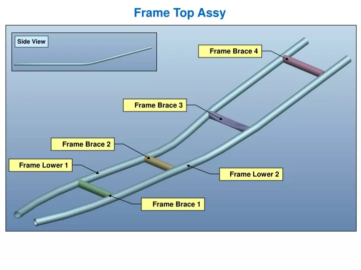
Frame Top Assy Side View Frame Brace 4 Frame Brace 3 Frame Brace 2 Frame Lower 1 Frame Lower 2 Frame Brace 1
Assembly Structure These features housed in the skeleton control nearly everything about the top level assembly and it’s subcomponents from a single location. We’ve kept the skeleton very simple with relatively few features. Skeleton Structure In some way, all six of the subcomponents rely on the skeleton for reference information. When the skeleton is modified, the parts will update to reflect the changes. Top Level Assembly Structure
Skeleton Structure The skeleton part for the sample frame assembly is shown below. There’s not much to see! Literally all we have are a few sketched lines, datum planes, and points. Skeleton models can be as complex or as simple as the designer wishes. This skeleton controls the major shape and dimensions of the frame. It also controls the location of the cross braces. This skeleton does not control tube diameter or wall thickness. There are also are a few details to the individual cross braces that aren’t controlled here. We could modify the skeleton to control these features if we wished. This would make the skeleton more complex and, therefore, more difficult to understand. However, the cross braces would require less detail thus they would become much simpler. The art of using top-down design is in finding the right balance between skeleton simplicity and usefulness. You want your skeleton to be just complex enough to capture major design requirements but not so complicated that it becomes cumbersome. Skeleton Top View Skeleton Side View
Features of the Sample Frame Assembly To increase the value of this sample frame, I made the components using various techniques. All four cross braces are made slightly differently to demonstrate the multiple ways you can build the model. As you progress in your mastery of Pro/E, it’s helpful to learn multiple ways to achieve the same effect. Sometimes there’s not one “best” way to perform a task. Other times there are multiple comparible techniques that appear equivalent yet they differ in small ways. These differences are often significant and valuable. The next slides detail each part, how it was created, and what techniques are used. The parts are labeled below for reference. Top Assy View
Frame Lower 1 & 2 Copy Geometry – copies geometry from the skeleton In this case, a single trajectory curve is copied from the skeleton. This curve will be used as the basis of the Variable Section Sweep (next feature) Variable Section Sweep – Creates Solid Tube I sketched a 1.00” diameter circle to use as the section for this feature. I could have activated the thickness option for this feature which would have made the tube hollow. This would have been a nice convenience. However, I did not use thickness because I needed the a solid tube to demonstrate techniques for performing cuts to the cross braces later. For now the object remains a solid tube. We’ll change this at the very last step to incorporate the thickness. Model Tree Frame Lower 2 Frame Lower 1 These items are mirrors of each other even though it’s hard to tell from these views
Frame Brace 1 Copy Geometry – copies geometry from the skeleton In this case, only two points are copied from the skeleton (PNT0 and PNT5). The blue trajectory lines for the lower frame tubes were notcopied from the skeleton. Why do they show up?? The “Cut Out” features bring them automatically (an unfortunate side effect). Pipe – Creates Solid or Hollow tube by connecting datum points I used the two points copied from the skeleton to create this pipe. I used a 1.00” outer diameter and used the “Hollow” option to give a wall thickness of .090” to the pipe. Standard geometry pipes like this are rarely used. Most designers do not like them because they have several oddball artifacts that make them a hassle to use in drawings (such as centerlines that are difficult to turn off). They’re also not very easy to control because they rely heavily on datum points. They’re considered a throwback to an older age of Pro/ENGINEER that has largely been forgotten. Model Tree Cut Out – Special feature only available in assembly mode which can be used to cut geometry from one part using a second part as a cutting tool. A Cut Out is an assembly feature. Why does it show up here in the part? This is an idiosyncrasy of the Cut Out feature. You have to create it at the assembly- but it shows up as a feature down at the part level. In this case, I used Frame Lower 1 and Frame Lower 2 to cut notches into the brace. We’ll discuss this more later. Cut Out was used to make the notches Frame Brace 1 (Geometry Only) Frame Brace 1 (with References)
Frame Brace 2 Copy Geometry – copies geometry from the skeleton In this case, only two points are copied from the skeleton (PNT1 and PNT6). Pipe – Creates Solid or Hollow tube by connecting datum points I used the two points copied from the skeleton to create this pipe. I used the same 1.00” outer diameter and wall thickness of .090” as Frame Brace 1. Model Tree Extrude – This is an extruded CUT feature. For this piece, I used an extruded cut to create the notches in the brace. Using the two points copied from the skeleton (PNT 1 and PNT 6) as references, I sketched two circles of 1.00” diameter and used them to cut the brace. This is just a basic cut feature with no ties to other components or the skeleton. Extruded Cut Detail Extruded Cut (above) was used to make the notches Frame Brace 2 (Geometry Only) Frame Brace 2 (with References)
Frame Brace 3 Copy Geometry – copies geometry from the skeleton Two points are copied from the skeleton (PNT2 and PNT7). Both Frame Lower 1 and Frame Lower 2 were also copied using “Solid Surfaces” option. Swept Blend (& 3 control sketches) – Creates a flattened tube with variable geometry. I used a Swept Blend feature in an attempt to approximate a flattened tube. This is just one technique to flatten a tube. I created three sketches: one for the sweep path, one for the tube in its circular state, and one for the tube in its flat state. I used relations to insure the same perimeter/circumference would be maintained at all times. I also turned on options to keep the cross-section of the blend consistent to make the geometry as accurate as possible. Points inside this feature control where the flat begins/ends. Model Tree Solidify – This is a Solidify Cut feature. Instead of simply solidifying the copied lower frame tubes (see Copy Geometry above), we perform a Solidify with Cut Option activated. This uses the resulting solids as cutting tools to notch the brace. Frame Lower 1 & 2 were copied as solid surface references (explained later) Solidify with Cut Option was used to make the notches Frame Brace 3 (Geometry Only) Frame Brace 3 (with References)
Frame Brace 4 Copy Geometry – copies geometry from the skeleton Two points are copied from the skeleton (PNT3 and PNT8). Both Frame Lower 1 and Frame Lower 2 were also copied using “Solid Surfaces” option. Variable Section Sweep (& control sketch) – Creates a swept round hollow tube. I used a variable Section Sweep feature with a sketched trajectory. The sketch is simply a line connecting the two reference points copied from the skeleton (PNT3 and PNT8). This is just demonstrating yet another way to create a hollow tube brace. Solidify – This is a Solidify Cut feature. This is the same type of feature used in Frame Brace 3 (see previous slide) Model Tree Offset & Round – Creates a welding gap & performs weld prep by breaking sharp edges An offset feature is capable of extending part surfaces in both positive and negative directions. In this case we extended the surfaces of the notches in a negative direction to leave greate a small weld gap between the brace and the lower tube. Additional welding prep operations were simulated using the round feature. See later slides for explanations. Solidify with Cut Option was used to make the notches. Offset and Round features represent weld allowance and prep Frame Lower 1 & 2 were copied as solid surface references (explained later) Frame Brace 4 (Closeup View with Some Refs Removed) Frame Brace 4 (Geometry Only) Frame Brace 4 (with References)
Skeleton Sketches (For Lower Frame1 & 2) – creates both sides of the lower frame profile Making each side of the lower frame profile a separate sketch makes it easier to copy features from the skeleton later. In addition, it allows us to use the Intersect feature later to create 3D curves. The geometry for Lower Frame 2 is mirrored from Lower Frame 1… so modifying one will modify both. Sketch – Creates a side profile for the lower frame This side profile will be used in combination with the two sketches above to create a 3D curves using the Intersect function below. Model Tree Intersect – Combines two planar curves by projection into a single 3D curve By selecting the sk_lower_frame_bend sketch and one of the two sk_lower_frame sketches, we can use EditIntersect to create a 3D curve. Points – Points are placed on the 3D curves measured from a datum plane. These points control the location of the 4 cross braces. If the points move, the braces move, too. The locations of the points are linked so if one set moves, they both move. See next slide for explanation of how to create a 3D curve usingtwo planar sketches and the Intersect feature Skeleton before performing Intersect feature Final Skeleton
How to Create a Multi-Plane (3D) Curve Note that from the top and front both curves appear to start and stop at the imaginary line. This is an important consideration when merging two planar sketches into one 3D curve. Top View Front View (sk_lower_frame_bend is shown in RED) Model Tree Another important consideration is that the sketches must be perpendicular (normal) to each other. Isometric View (Notice all sketches exist in only a single plane)
How to Create a Multi-Plane (3D) Curve Continued To create a 3D curve, select any two perpendicular sketches (hold CTRL while choosing them). Next, select EditIntersect from the top level Pro/E menu. Model Before Intersect Operation Notice the 3D curves have been created. The sketches used to create them have been hiddenautomaticallyin the model tree (shown right). Automatically Hidden New Intersect features represent the 3D curves Model After Intersect Operation Model Tree
How to Copy Geometry from the Skeleton as a Reference The essence of top-down design is controlling high level design constraints and parameters at the skeleton level and using those parameters to drive part design. The next few slides demonstrate one possible technique for copying references from the skeleton model to drive the design of individual components. There are other methods of gathering references. The example below shows how the references for frame_brace4.prt were gathered and how those references were used to model the final part. Step 1: Starting from the top level assembly, select InsertComponentCreate. Enter the name of the new component in the dialog box (shown lower right). In this case, I’ve entered “frame_brace4”. Select OK. Model Tree at Start of Procedure
How to Copy References from the Skeleton (Continued) Step 2: From the Creation Options dialog box, select one of the options to place your new model. Place the model into your assembly. I’m skipping some of the details of this step because there are many possible ways to assemble your new part. The image below shows frame_brace4 inserted into the top level assembly. The model tree is also shown for reference. The red datums belong to frame_brace4.prt The points are contained in frame_top_assy_skel.prt We’ll copy them into frame_brace4.prt as references Model Tree after frame_brace4.prt is assembled Top Assembly Shown with frame_brace4.prt assembled
Green Star indicates part is active How to Copy References from the Skeleton (Continued) Step 3:Activate frame_brace4.prt within the top level assembly. To Activate the part, select it from the Model Tree, right-click and select Activate. A green star (shown below) will highlight next to the part symbol if the part has been activated. Note: The part may already be activated. If the green star is present, there’s no need to do anything because the part is already active. Model Tree with frame_brace4.prt activated Step 4: From the top level Pro/E menu, select InsertShared DataCopy Geometry. Make sure your dashboard options are set as displayed below. Make sure the indicated icon below has been de-selected (this is the Publish Geometry option which we will not use in this example). The BLUEcircled icon should be activated. The RED circled icon should not be activated. For many users, this is turned on by default. De-select it if necessary.
How to Copy References from the Skeleton (Continued) Step 5: Select the References tab (circled in BLUE) to expand it. Under this tab there are three sub types available for selection: surface sets, chain, and references. The expanded references tab is shown below with descriptions of each sub type.Click in the References sub type area (highlighted below in green) before proceeding to the next step. Surface Sets – gathers surfaces, quilts, and solid objects Click in this area to enable surface gathering including solid objects. We’ll do this in the next few steps. For now, ignore it. Chain – gathers edges, curves, and sketches Click in this area to enable edge, curve, and sketch gathering. We will not use this subtype in this example. References – this subtype gathers datum planes, points, axes, coordinate systems, and other miscellaneous features Click in this area to enable datum gathering. We will use this subtype to gather the datum points from the skeleton in the next step.
How to Copy References from the Skeleton (Continued) Step 6: Select the two points shown below in RED. Select the GREEN check mark to complete the feature. Note the two reference points show up here Two points in RED selected as references
How to Copy References from the Skeleton (Continued) Step 7: From the top level Pro/E menu, select InsertShared DataCopy Geometry to copy additional references. Make sure your dashboard options are still set as in Step 4. Expand the References tab. Click in the Surface Sets sub type area (highlighted below in green). Pick any surface to turn it pink. Right-click to select Solid Surfaces from the pop up menu Pop Up Menu frame_lower1 with a single surface selected (in pink) Step 8: Pick on any surface of the frame_lower1.prt as shown above. The surface will turn pink. Right-click and select Solid Surfaces from the pop up menu (shown above right). The entire frame_lower1.prt should turn pink. Select the GREEN check mark to complete the feature.
How to Copy References from the Skeleton (Continued) Step 9: One last time, from the top level Pro/E menu, select InsertShared DataCopy Geometry to copy additional references. Make sure your dashboard options are still set as in Step 4. Expand the References tab. Click in the Surface Sets sub type area (highlighted below in green). Pick on any surface of the frame_lower2.prt. Right-click to select Solid Surfaces from the pop up menu. Complete the feature by selecting the GREENcheck mark. Pick any surface to turn it pink. Right-click to select Solid Surfaces from the pop up menu frame_lower2 shown with all Solid Surfacesselected
Using References to Drive Part Design Step 10: Open frame_brace4.prt to view the copied references. Although the copied lower frame pieces appear to be solid geometry, they are actually only copied surfaces (created using the Solid Surfaces) option from Steps 8&9. Later we will solidify these surfaces into solid geometry and use them to cut notches into the brace. Toggling into Wireframe Mode reveals that these copied features are surfaces. Surfaces turn purple in wireframe mode where solid geometry turns white. Surfaces turn purple in wireframe frame_brace4 shown in Shaded Mode frame_brace4 shown in Wireframe Mode
Using References to Drive Part Design Step 11: Create a simple sketch connecting PNT3 and PNT8 (which were copied from the skeleton). In sketcher, be sure to select the two points as references. Draw a line connecting them to use as a trajectory in the next step. Sketch (blue line) connecting points frame_brace4 shown with sketch connecting points frame_brace4 after Sweep Step 12: Create a Variable Section Sweep using the sketch from the previous step as the trajectory. Sketch a 1.00” diameter circle with a thickness of .090” for the section. The result it shown above (right). Several other types of features could also be used to make this geometry.
Using References to Drive Part Design Step 13: Select one of the copied surfaces from the screen or the Model Tree as shown. From the top Pro/E menu, select EditSolidify. Select the Cut option from the dashboard as shown. Complete the feature by selecting the check mark. Notice the copied geometry automatically goes away leaving a notch cut out from the brace. Repeat this for the step for the other side. Select one of the surface copies from the screen or the Model Tree. Select the Cut option here Solidify Dashboard with Cut Option Activated Model Tree Notch cut out of brace as a result of the Solidify Cut feature. Repeat procedure to cut out other side before moving to next step. frame_brace4.prt after the first Solidify Cut feature
Using References to Drive Part Design Step 14: To create a small gap between the notched surface and the lower frame, we’ll use an Offset feature. Select the surfaces of the notch cuts as shown below. Hold CTRL to select both surfaces at once.From the top Pro/E menu, select EditOffset. Set the dashboard to the Expand feature shown below circled in BLUE. Set the offset to .060 and complete the feature. Select these two surfaces Surfaces of notch cuts shown selected in pink Set to .060 offset Brace Part Shown After Offset (Part has been shortened by .060 on each side) Offset Dashboard Set to Expand Mode and .060 offset
Using References to Drive Part Design Step 15: To further simulate weld prep for this piece, we’ve added small rounds. This simulates breaking sharp edges before welding. Round the edges shown to .020” radius. .060 Weld Gap created by Offset Round The Edges Shown to .020 radius Final Assembly showing Weld Gap Final Part Showing Offset & Round Detail
How to Modify the Skeleton to Control the Design These reference sketches were automatically hidden during creation of the Intersect features (this occurs by default). Temporarily unhide them to make modifications easier. Skeleton Model Tree Modify dimensions of datum points to change locations of the four cross braces Modify dimensions on sk_lower_frame_bend to change bend angle, location, or angle Modify dimensions on sk_lower_frame1or sk_lower_frame2 to modify the shape of the frame (in top view) After making modifications in the skeleton, regenerate the top level assembly to see the effects of those modifications on the overall assembly. All parts will update automatically to reflect the changes to the skeleton. Skeleton Model with All Features Shown
Revisiting The Lower Frame Tubes Back on Slide #5, we purposely allowed the lower_frame1 and lower_frame2 components to remain SOLID tubes. In real life, these would certainly be hollow tubes like the cross braces. Let’s go back to these lower frame tubes and make them hollow. Throughout this example, we’ve demonstrated multiple methods to model the cross brace components. We’ve used a variety of features to generate the tubes and create notches in them. So then, which of the modeling techniques presented is the best? As stated previously: So far, all of the techniques demonstrated in this example appear to work equally well by creating virtually identical geometry. This final step will reveal deficiencies in some of our modeling techniques. Overcoming these deficiencies will necessitate changes in the models. This is where the subtle differences in features become “significant and valuable”. Sometimes there’s not one “best” way to perform a task. Other times there are multiple comparible techniques that appear equivalent yet they differ in small ways. These differences are often significant and valuable. Frame Lower 1 Original (Solid Tube) Frame Lower 2 Original (Solid Tube)
Revisiting The Lower Frame Tubes (Continued) Instructions: Open bothlower_frame1.prtand lower_frame2.prt. From the top Pro/E menu, select InsertShell. Select BOTH circular end surfaces of the tube as shown below. Enter a value of .090 for the shell thickness.Complete the feature. Perform the same operations to both parts. Open the top level assembly frame_top_assy.asm and regenerate to update all components. Select the circular end surfaces on both ends End surface selected Frame Lower 1 w/ Shell Dashboard Activated Select the circular end surfaces on both ends Frame Lower 1 with Shell Surfaces Selected
Frame Brace 1 Pipe w/ Cut Out feature for notches Frame Brace 2 Pipe w/ Extruded Cut for notches Frame Brace 3 Swept Blend w/ Solidify Cut for notches Frame Brace 4 Var. Section Sweep w/ Solidify Cut for notches Revisiting The Lower Frame Tubes (Continued) Beforethe shell operation in frame_lower1 and frame_lower2, the cross brace parts looked like this: Afterthe shell operation and after regenerating the top level assembly, the cross brace parts look like this: Frame Brace 1 Pipe w/ Cut Out feature for notches Frame Brace 2 Pipe w/ Extruded Cut for notches Frame Brace 3 Swept Blend w/ Solidify Cut for notches Frame Brace 4 Var. Section Sweep w/ Solidify Cut for notches This is the only component that still has the correct notches!
Which Technique Works Best? While all of the techniques used to create the tubes (Pipe, Swept Blend, Variable Section Sweep) all worked properly, only the Extruded Cut created the notches correctly. This is because the other features used to create notches (Assembly Cut Out and Solidify Cut) both relied on the solid geometry of the lower frame tubes as references. When the lower frames were solid, the Cut Out and Solidify Cut features created good notches. When the lower frames were converted to hollow tubes, these features left voids which destroyed the notches. In this case, the best course of action would be to redefine the notch cuts in all frame braces to use Extruded Cuts as in frame_brace2.prt. This will resolve the errors allowing all notches to regenerate correctly. The original “bad” notches and solid lower frame tubes have been saved with the sample assembly and parts for this demonstration. This allows you to examine these features for yourself, modify dimensions, and test the solid/hollow problem. Good luck!! Final Frame Top Assembly