Download
1 / 101
1.01k likes | 1.03k Vues
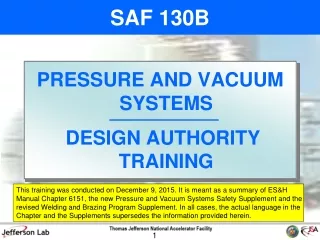
SAF 130B. PRESSURE AND VACUUM SYSTEMS DESIGN AUTHORITY TRAINING. 1. Course Overview. Why Are We Here? JLab and other DOE Lab Performance 10CFR851 Requirements Hazard Avoidance Techniques Revised ES&H Manual Chapter 6151 Overview / Major differences The New Pressure and Vacuum Systems

E N D
SAF 130B PRESSURE AND VACUUM SYSTEMS DESIGN AUTHORITY TRAINING 1
Course Overview Why Are We Here? JLab and other DOE Lab Performance 10CFR851 Requirements Hazard Avoidance Techniques Revised ES&H Manual Chapter 6151 Overview / Major differences The New Pressure and Vacuum Systems Safety Supplement Overview / Major differences Revised Welding and Brazing Program Supplement Overview / Major differences Future Plans 2
JLab and other DOE Lab Performance Why revise the Pressure Safety Program? • Several accidents have occurred here and at other DOE sites. • Our documentation has some holes. • Independent program review by George Rawls, SRNL Sr Fellow Engineer: • Focus on ASME Code requirements • Clearly identify required examinations, both welding and mechanical • Clarify Owner’s Inspection function • Create approval process for overpressure protection by system design PressureTest Form This is a snapshot of some Pressure System Folders. Red means folder is empty. Form Is Blank 3
“Contractors must establish safety policies and procedures to ensure that pressure systems are designed, fabricated, tested, inspected, maintained, repaired, and operated by trained and qualified personnel in accordance with applicable and sound engineering principles.” “Contractors must establish safety policies and procedures to ensure that pressure systems are designed, fabricated, tested, inspected, maintained, repaired, and operated by trained and qualified personnel in accordance with applicable and sound engineering principles.” “Contractors must ensure that all pressure vessels … and supporting piping systems conform to: (1) The applicable ASME Boiler and Pressure Vessel Code (2) The applicable ASME B31 Code for Pressure Piping (3) The strictest applicable state and local codes” “When national consensus codes are not applicable (because of pressure range, vessel geometry, use of special material, etc.), contractors must implement measures to provide equivalent protection…” 4
§851.24 Functional Areas (excerpt) • Contractors must have a structured approach to their worker safety and health program… • §851.25 Training and information (excerpt) • Contractors must provide training and information to workers who have worker safety and health program responsibilities that is necessary for them to carry out those responsibilities • §851.26 Recordkeeping and reporting (excerpt) • (a) Recordkeeping. Contractors must: • Establish and maintain complete and accurate records of all hazard inventory information, hazard assessments, exposure measurements, and exposure controls. PROCEDURES TRAINING DOCUMENTATION 5
Why Are We Here? Hazard Avoidance Techniques design, fabricate, test according to ASME or other Code operate within design parameters use only for designed purpose do not apply heat unless specifically authorized donotworkon systems withoutauthorizationandtraining perform maintenance, report damage or defects use Lock, Tag, Try to depressurize/repressurize • perform routine in-service inspections 6
Why Are We Here? Hazard Avoidance Techniques design, fabricate, test according to ASME or other Code operate within design parameters use only for designed purpose do not apply heat unless specifically authorized donotworkon systems withoutauthorizationandtraining perform maintenance, report damage or defects use Lock, Tag, Try to depressurize/repressurize Design Authority • Design Requirements • System Parameters • Code of Record • Operating Conditions • Calculations • Material Selection • Component Selection • Pressure Relief • Welding Parameters • Drawings • P&ID • Reviews • Purchasing • Receipt Inspection • Fabrication • Assembly • Installation • Welding Examination • Mechanical Examination • Pressure Testing • Final Inspection • System Turnover • Documentation System Owner System Owner Design Authority may delegate tasks but not responsibility System Owner System Owner System Owner System Owner • perform routine in-service inspections System Owner 7
Course Overview Why Are We Here? JLab and other DOE Lab Performance 10CFR851 Requirements Hazard Avoidance Techniques Revised ES&H Manual Chapter 6151 Overview / Major differences The New Pressure and Vacuum Systems Safety Supplement Overview / Major differences Revised Welding and Brazing Program Supplement Overview / Major differences Future Plans 8
Revised ES&H Manual Chapter 6151 • Content was changed to concentrate on purpose, scope and responsibilities • New language was added to clarify “legacy” systems • Procedural steps were removed and all technical appendices were replaced with the new Pressure and Vacuum Systems Safety Supplement • Newly identified functions: • System Owner • Technician • Vessel Inspection Coordinator “…to ensure that all personnel at Jefferson Lab involved in the construction, repair, alteration and operation of pressure and vacuum systems are cognizant of the hazards associated with these systems and construct, repair, alter and operate these systems in a safe manner.” Pre-2008 systems are identified as pressure systems and subject to operation, maintenance, in-service inspection, repair and alteration procedures Pressure & Vacuum Systems Safety Supplement Part 1 General Program Information Part 2 Pressure System Construction Part 3 Equivalent Measures Part 4 Overpressure Protection Part 5 Repair and Alteration Part 6 Pressure and Leak Testing Part 7 Vacuum Systems Part 8 Operation and Maintenance Part 9 In-service Inspection Program Part 10 Mandatory Forms Responsible for the operation, maintenance and inspection of a pressure system Performs work functions for the construction, testing, operation, maintenance, inspection, repair and alteration of a pressure system Responsible for coordinating in-service inspection of ASME vessels, etc. 9
JLab Definition of Pressure System Pressure System: (OLD) A connected set of piping, piping components and/or pressure vessel(s) used to either convey or contain a fluid under pressure above 0 psig. Pressure sources, fittings, pressure relief devices and associated hardware such as gages and regulators are also integral parts of the pressure system. Vacuum systems which cannot be protected against pressurization exceeding 15 psig from all credible pressure sources are considered pressure systems. Pressure System: (NEW) Any combination of vessels, piping, instrumentation (e.g. gauges), and/or equipment (e.g. pumps or compressors) either containing a fluid under internal pressure or exposed to external fluid pressure. Note that vacuum systems are a subclass of pressure systems. Vacuum systems can be especially hazardous when backfilling or purging. 10
“Excepted” Systems RED IS NEW CONTENT • Excepted Pressure Systems: (check ES&H Manual 6151 for details) • Any system where all of the following are met: • Max. pressure cannot exceed 15 psid including failure modes • Fluid is non-flammable., nontoxic and not damaging to human tissue • Design temperature is between -20F and 366F • Stored energy is below 10000 ft-lbs • Any system with a total stored energy (thermo-mechanical and chemical) less than 1000 ft-lb provided the system fluid is not damaging to human tissue • Excepted Pressure Systems: (check ES&H Manual 6151 for details) • Any system where all of the following are met: • Max. pressure cannot exceed 15 psid including failure modes • Fluid is non-flammable., nontoxic and not damaging to human tissue • Design temperature is between -20F and 366F • Stored energy is below 10000 ft-lbs • Any system with a total stored energy (thermo-mechanical and chemical) less than 1000 ft-lb provided the system fluid is not damaging to human tissue 11
“Excepted” Systems RED IS NEW CONTENT “Excepted” doesn’t mean hazards aren’t real for those systems! Hazard avoidance must always be considered for any pressurized system! • Gas/liquified gas cylinders (covered by ES&H Manual 6150) • USDOT covered vehicle pneumatic and hydraulic systems • SCBA air cylinders • Domestic water heaters with a capacity less than 120 gal, less than 210F and heat input below 200000 BTU/hr • Domestic appliances covered by national standards • ASHRAE compliant systems and devices • Roof and floor drains, plumbing and sewers • Domestic hot, cold and grey water piping • Piping for hand tools downstream of stop valve • Instruments (not instrument piping/tubing) • Fire protection systems (covered by ES&H Manual 6900) • Gas/liquified gas cylinders (covered by ES&H Manual 6150) • USDOT covered vehicle pneumatic and hydraulic systems • SCBA air cylinders • Domestic water heaters with a capacity less than 120 gal, less than 210F and heat input below 200000 BTU/hr • Domestic appliances covered by national standards • ASHRAE compliant systems and devices • Roof and floor drains, plumbing and sewers • Domestic hot, cold and grey water piping • Piping for hand tools downstream of stop valve • Instruments (not instrument piping/tubing) • Fire protection systems (covered by ES&H Manual 6900) 12
Course Overview Why Are We Here? JLab and other DOE Lab Performance 10CFR851 Requirements Hazard Avoidance Techniques Revised ES&H Manual Chapter 6151 Overview / Major differences The New Pressure and Vacuum Systems Safety Supplement Overview / Major differences Revised Welding and Brazing Program Supplement Overview / Major differences Future Plans 13
New Pressure & Vacuum Systems Safety Supplement Table of Contents Part 1 General Program Information Part 2 Pressure System Construction Part 3 Equivalent Measures Part 4 Overpressure Protection Part 5 Repair and Alteration Part 6 Pressure and Leak Testing Part 7 Vacuum Systems Part 8 Operation and Maintenance Part 9 In-service Inspection Program Part 10 Mandatory Forms Table of Contents Part 1 General Program Information Part 2 Pressure System Construction Part 3 Equivalent Measures Part 4 Overpressure Protection Part 5 Repair and Alteration Part 6 Pressure and Leak Testing Part 7 Vacuum Systems Part 8 Operation and Maintenance Part 9 In-service Inspection Program Part 10 Mandatory Forms The Supplement should be considered a “living” document. We understand that this program will evolve and we chose this “Supplement” format to simplify the revision process. Open communication between all parties involved is vital for the success of this program. If you have questions or comments please bring them to the Pressure Systems Committee. Use the Website as a resource. The first section includes general Code discussion, responsibilities, qualifications and documentation requirements 14
Part 1: General Program Information BPVC: (excerpts from Introduction) This Code contains mandatory requirements, specific prohibitions, and nonmandatory guidance for construction activities and inservice inspection and testing activities. The Code is not a handbook and cannot replace education, experience, and the use of engineering judgment. Engineering judgments must be consistent with Code philosophy, and such judgments must never be used to overrule mandatory requirements or specific prohibitions of the Code. B31: (excerpts from Introduction) The Code sets forth engineering requirements deemed necessary for safe design and construction of pressure piping. All applicable requirements of the selected Code Section shall be met. The Code is not a design handbook; it does not do away with the need for the designer or for competent engineering judgment. • PS Committee assumes duties of jurisdictional authority • Arbitration and interpretation of Code/policy issues • Provide guidance when requested • Arbitrate and oversee in-service inspection issues • ASME Code • Code of Record shall be identified (CODE + EDITION) • What does “Code is not a handbook” mean? • Interpretation of Code functions 15
Part 1: General Program Information • Design Authority Responsibilities: • Ensure safety of the public, personnel and the environment are primary considerations. • Ensure construction, alteration, repair and documentation meet the Supplement • Employ, as required, the expertise available through other DAs, the QA/CI Inspector, Welding Committee and the Pressure Systems Committee … • Define the in-service inspection requirements • Define the operational requirements • Define special maintenance requirements • Responsibilities and Qualifications are summarized for all functions involved The list continues to summarize tasks involved with meeting Supplement requirements. Note the final 3 are not new but are now given a structured approach: 16
Part 1: General Program Information • Responsibilities and Qualifications are summarized for all functions involved • Required Documentation • Consult with PSC Designee to create a PS ID number: PS-ABC-XX-123 • Create a meaningful title • Carefully choose the system type designation (ABC) and title. This information will be used to inventory the system. • Repairs and alterations should refer back to the original PS ID number. If a new number is used, the DA must follow the complete documentation and process requirements for a new system. Bridget Paul Ext. 7306 17
Part 1: General Program Information Engineering: Design Calculations Reviews Design Drawings Overpressure Protection SOW Fabrication and Procurement Procurement Welding, Brazing, and Soldering Material and Instrument Certifications Mechanical Examinations Leak and Pressure Testing Vessels Overpressure Protection Final Walkthrough Operation and Maintenance System Turnover Operations Maintenance Alterations Alteration 1… Alteration 2… Repairs Repair 1… Repair 2… In-Service Inspections Miscellaneous Not all documentation is applicable! If a process step is applicable, associated documentation shall be filed in the appropriate folder. • Responsibilities and Qualifications are summarized for all functions involved • Required Documentation • Consult with PSC Designee to create a PS ID number: PS-ABC-XX-123 • Create a meaningful title • Create a project folder with subfolders Exemption for ASME B31.5, B31.9, and B31.3 Cat “D”: DA may choose an alternative: • System Number and title as normal • Top system folder with notations on alternate filing location(s) • Single subfolder labeled “Pressure System Forms” where all applicable forms must be filed. • Documentation must available within 5 working days upon formal request. 18
Part 1: General Program Information Mandatory Forms: PS-1 Project Cover Sheet PS-2 Overpressure Protection by Design PS-3 Technical/Peer Review PS-4 Vessel Registration PS-5 Relief Device Registration PS-6 Final Mechanical Examination PS-7 Pressure/Leak Test Record PS-8 Final Walkthrough PS-9 Pressure System Turnover PS-10 Pressure Equipment ISI PS-11 ASME Vessel/Relief Device ISI PS-12 Relief Device ISI 19
Part 1: General Program Information Mandatory Forms: PS-1 Project Cover Sheet PS-2 Overpressure Protection by Design PS-3 Technical/Peer Review PS-4 Vessel Registration PS-5 Relief Device Registration PS-6 Final Mechanical Examination PS-7 Pressure/Leak Test Record PS-8 Final Walkthrough PS-9 Pressure System Turnover PS-10 Pressure Equipment ISI PS-11 ASME Vessel/Relief Device ISI PS-12 Relief Device ISI Minimum required before initial startup 20
New Pressure & Vacuum Systems Safety Supplement Table of Contents Part 1 General Program Information Part 2 Pressure System Construction Part 3 Equivalent Measures Part 4 Overpressure Protection Part 5 Repair and Alteration Part 6 Pressure and Leak Testing Part 7 Vacuum Systems Part 8 Operation and Maintenance Part 9 In-service Inspection Program Part 10 Mandatory Forms 21
Part 2: Pressure System Construction 1 General 2 Pressure Vessels 3 Pressure Piping 4 Design 5 Reviews 6 Use of Unlisted Components 7 Materials 8 Welding, Brazing and Soldering 9 Examination 10 Inspections 11 System Turnover 22
Part 2: Pressure System Construction 1 General construction: design review purchasing fabrication assembly installation examination inspection testing documentation 23
Part 2: Pressure System Construction 1 General Pressure systems initiated after January 4, 2016 shall meet requirements in Part 2 For in-process systems, DA can meet Part 2 or follow existing Rev. 3.4 and Complete PS-1 Register vessels and relief devices using PS-4 and 5 Create and file a P&ID Complete Final System Walkthrough and PS-8 Complete System Turnover and PS-9 24
Part 2: Pressure System Construction 2 Pressure Vessel Construction Pressure vessels shall be constructed, to the greatest extent reasonably possible, in full compliance with the ASME Boiler and Pressure Vessel Code 2 categories: ASME Pressure Vessels Excluded Vessels A Code of Record shall be identified whether or not the Code can be fully applied • EXCLUDED VESSELS: • Excepted/excluded by BPVC • Considered to be equipment • Requires unlisted material • Operating conditions outside of BPVC scope • Special geometry • Considered to be instrumentation • Considered as internal piping • Scientific or functional requirements preclude compliance • Cannot be tested or examined to Code 25
Part 2: Pressure System Construction 2 Pressure Vessel Construction 26
Part 2: Pressure System Construction 2 Pressure Vessel Construction • Vessel Numbering B# - PS – ABC – XX – 123 - V# Bldg # Sequential # Pressure System ID # • Tagging – vessel # must be conspicuously and durably displayed on vessel • Registration – complete Form PS-4 and forward to Vessel Inspection Coordinator 27
Part 2: Pressure System Construction 3 Pressure Piping Construction Pressure piping shall be constructed, to the greatest extent possible, in compliance with the ASME B31 Code for Pressure Piping 2 categories: ASME B31 Pressure Piping Excluded Elements A Code of Record shall be identified whether or not a B31 Code can be fully applied • EXCLUDED ELEMENTS: • Excepted/excluded by all B31 Codes • Considered to be equipment • Requires unlisted material • Operating conditions outside of B31 scope • Special geometry • Considered to be instrumentation • Considered as internal piping • Scientific or functional requirements preclude compliance • Cannot be tested or examined to Code 28
Part 2: Pressure System Construction PS-LCW -16-001 LCW cooling for something Sketch 333044 03493049 Dave Meekins TBD x 4 Vessel and Piping Design: • DA ensures calculations required by Code, engineering design and JLab are performed and reviewed • Engineering design must be formalized by SOW. Form PS-1 Pressure System Cover Sheet is required for each system and may be used as the SOW. • The Supplement is not a design handbook. The DA must consider many elements… 2014 X Water Cat D 100 F 60 psi 101-PS-LCW-16-001-01 >1000 ft-lbs Cooling for something important in Hall A wrong right 29
Part 2: Pressure System Construction Design Considerations • Design life of the system • Properties of the confined fluid • All operating conditions – start-up, normal, shutdown, stand-by and emergency • Need for maintenance and in-service inspection • Future changes to design conditions • Protection against system failure • Suitable material selection • External forces including thermal, seismic and wind (if applicable) 30
Part 2: Pressure System Construction 5 Reviews: • Technical Review – formal review by another DA • Peer Review – formal review by at least one DA not associated with the project and not a member of the same group • Form PS-3, Technical/Peer Review Record must be completed 31
Part 2: Pressure System Construction 6 Unlisted Components: • B31 allows use of unlisted components with consent of the Owner.DA assumes this role. • DA shall ensure that all calculations are performed, reviewed and documented. • Qualify unlisted components according to Code. (Note that equivalent measures may not be required) • Unlisted piping components must meet B31.3 304.7.2 32
Part 2: Pressure System Construction 7 Materials: • DA ensures that materials are compatible with fluid service, system fluids and engineering design • Unlisted materials require Equivalent Measures • Material selection considerations: • Materials of unknown origin shall not be used. DA determines extent of documentation required. 33
Part 2: Pressure System Construction 8 Welding, Brazing and Soldering: • Pressure Boundary – Joint design, personnel and procedures must meet JLab Welding & Brazing Supplement and the applicable ASME or NB Code • Support Elements – Joint design, personnel and procedures shall meet JLab Welding & Brazing Supplement and the applicable ASME or AWS Structural Welding Code • DA completes Design Parameter Form or equivalent • Examinations and Inspections must follow Code and reports must be filed with system documentation 34
Part 2: Pressure System Construction 9 Examinations: • Examinations are not Inspections! • DA ensures that all examinations required by Code, JLab policy and engineering design are completed and documented • 2 Categories of Examinations: Welding/Brazing – method (RT, UT, VT, etc.) chosen by DA, must meet Code Mechanical – in-process and final • Final mechanical examination is required after installation is complete. Document and file using Form PS-6 Mechanical Examination: • Materials, components (fittings, valves, etc) and products conform to specifications • Applicable procedures for assembly • Threaded, bolted and other joints conform to Code and engineering design • Alignment, supports and cold spring meet engineering design • Dimensional checks of components and materials Examination - observation, by suitable technique, of components, joints, and other elements either before, during or after construction. It may include verification of materials, components, dimensions, joint prep, alignment, welding, supports or assembly. Inspection – verification that all required examinations and tests have been completed and that documentation conforms to Code, JLab policy and engineering design. 35
Part 2: Pressure System Construction 10 Inspections: • All new pressure systems shall be inspected by a Pressure System Construction Inspector • This inspector witnesses final system pressure test (unless otherwise arranged) and completes the Final System Walkthrough (Form PS-8) and signs as Owner’s Inspector • Who is this Inspector? • Someone meeting B31.3 Para. 340.4 Qualifications of the Owner’s Inspector requirements: • DA with 5 years experience or • CWI or senior CWI with 5 years experience or • Authorized Piping Inspector with 5 years experience • Approved by Pressure Systems Committee • Independent from system design, fabrication, installation, testing and examination The Final System Walkthrough cannot be performed without actually “walking down” the system, checking pressure relief valves, etc. These items are for documentation control. Mike Martin Ext. 5515 and Jenord Alston Ext. 5859 are primary contacts. For specialized inspection, consult the list on the Pressure System Website. 36
Part 2: Pressure System Construction 11 System Turnover: • After walkthrough and before operation, DA formally turns system over to the System Owner • Using Form PS-9, DA defines and documents: operating requirements special maintenance requirements in-service inspection requirements • Both parties sign and date • Forward to Bridget Paul to prompt entry into “Operating Pressure Systems Database” Ensures the System Owner is identified and notified as well as prompting the new system to be added to the operating system database. 37
New Pressure & Vacuum Systems Safety Supplement Table of Contents Part 1 General Program Information Part 2 Pressure System Construction Part 3 Equivalent Measures Part 4 Overpressure Protection Part 5 Repair and Alteration Part 6 Pressure and Leak Testing Part 7 Vacuum Systems Part 8 Operation and Maintenance Part 9 In-service Inspection Program Part 10 Mandatory Forms 38
Part 3: Equivalent Measures • Equivalent measures shall be used to ensure a level of safety equal to or greater than that required by ASME Pressure Codes FOR EACH EXCLUDED ELEMENT. • Documentation shall include all of the following in addition to the standard: • Reason why the Excluded Element cannot fully comply with selected Code of Record • Specific Code requirements that cannot be met • Calculations required by Code, sound engineering principles, and the engineering design • Specifications for special examinations or inspections if applicable • Specific measures taken The most applicable Code of Record must always be identified 39
Part 3: Equivalent Measures • Measures taken to ensure a level of safety equal to or greater than ASME Pressure Code can include: • Extensive detailed analysis • Protective barriers • Secondary containment • Specialized testing • Protection of thin sections from accidental damage • Administration controls 40
Part 3: Equivalent Measures • The functions defined by ASME BPVC for Excluded Vessels shall be as follows: • The DA and System Owner assume the duties of the Owner/User • The DA assumes the responsibilities of the Manufacturer • The duties of the Inspectorare assumed by an In-house Inspector • A Peer Review of each Excluded Vessel and/or Element shall be performed. 41
New Pressure & Vacuum Systems Safety Supplement Table of Contents Part 1 General Program Information Part 2 Pressure System Construction Part 3 Equivalent Measures Part 4 Overpressure Protection Part 5 Repair and Alteration Part 6 Pressure and Leak Testing Part 7 Vacuum Systems Part 8 Operation and Maintenance Part 9 In-service Inspection Program Part 10 Mandatory Forms 42
Part 4: Overpressure Protection 1 General Requirements 2 Potential Causes of Overpressure 3 Relief Devices Exposed to Weather 4 Pressure Relieving Requirements 5 Overpressure Protection by Relief Device 6 Installation 7 Relief Device Registration 8 Overpressure Protection by System Design 43
Part 4: Overpressure Protection 1 General Requirements • Design must account for all reasonable sources of overpressure and mitigate them through relief devices, design or other method • For systems >15 psi, DA shall • Analyze possible failure modes and effects (simple or formalized) • Calculate relief capacity • Consider discharge effects (reaction forces, venting, environmental factors) • For Excluded Elements and Vessels (MAWP>15psi) use BPVC VIII D1 • Overpressure protection analysis requires a technical review 44
Part 4: Overpressure Protection 2 Potential Causes of Overpressure Overpressure results from disruption or unbalance of fluid flow or energy. Some causes include: 45
Part 4: Overpressure Protection 2 Potential Causes of Overpressure Overpressure results from disruption or unbalance of fluid flow or energy. Some causes include: 46
Part 4: Overpressure Protection 3 Relief Devices Exposed to Weather Consider the following: • Equip with bug screens • Protect exhaust from rain, ice and snow • Made from materials compatible with exposure 47
Part 4: Overpressure Protection • Pressure Relieving Requirements • DA shall determine largest credible relief capacity required and size relief devices appropriately • Max. allowable accumulation shall be in accordance with Code of Record (BPVC VIII D1 for Excluded) • Devices shall be sized such that total capacity is sufficient for calculated mass flow • Relief path shall be analyzed for capacity and pressure drop 48
Part 4: Overpressure Protection • Pressure Relieving Requirements (cont.) • Considerations for Overpressure from Exposure to Prolonged External Fire • Considerations for Overpressure due to the Loss of Insulating Vacuum • Exposure to external fire can result in very large relief loads • Excellent guidance for liquid hydrocarbon pool fire is in • API 521 Section 5.15 • JLab Fire Protection Engineer can provide guidance • Fire mitigation may be provided by preventative measures: • Adequate drainage, dykes to prevent pooling • Removal of brush, debris • Elimination or limitation of close flammable material • Fire suppression system • Insulation and fireproofing • Cryogenic Vacuum Insulation relief depends on many factors: • Fluid properties and chemistry • Geometry • Insulation type and thickness • Temperature gradient • Loss of insulating vacuum on high temperature surfaces may result in catastrophic failure, OSP or TOSP is required The heat transfer rate is critical in calculating required relief capacity. DA is encouraged to collaborate with other experienced DAs 49
Part 4: Overpressure Protection 5 Overpressure Protection by Relief Device Generally takes 2 forms: Reclosing (spring loaded) and non-reclosing (rupture disk) 50