Download
1 / 24
250 likes | 449 Vues
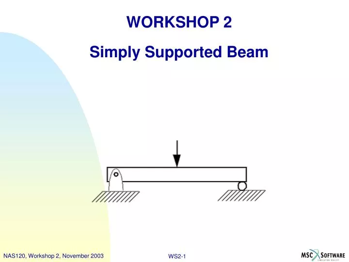
WORKSHOP 2 Simply Supported Beam. NAS120, Workshop 2, November 2003. WS2- 1. Problem Description Analyze a simply-supported beam with a concentrated load Beam dimension 1” x 1” x 12” E = 30 x 10 6 psi n =0.3 Load = 200 lb. P. P. Workshop Objectives

E N D
WORKSHOP 2 Simply Supported Beam NAS120, Workshop 2, November 2003 WS2-1
Problem Description • Analyze a simply-supported beam with a concentrated load • Beam dimension 1” x 1” x 12” • E = 30 x 106 psi • n =0.3 • Load = 200 lb P P
Workshop Objectives • A finite element model must be properly constrained to prevent rigid body motion. This workshop demonstrates how to properly constrain a model in 3-D space.
Suggested Exercise Steps • Create a new database and name it inadequate_constraint.db. • Create a solid to represent the beam. • Mesh the solid to create 3D elements. • Create in-plane boundary conditions. • Apply loads. • Create material properties. • Create physical properties. • Run analysis with MSC.Nastran. • View fatal errors in the .f06 file. • Add new boundary condition to properly constrain model. • Re-run the analysis. View the .f06 file. • Access the results file. • Plot results.
Step 1. Create New Database a a • Create a new database called inadequate_constraint.db • File / New. • Enter inadequate_constraint as the file name. • Click OK. • Choose Tolerance Based on Model. • Select MSC.Nastran as the Analysis Code. • Select Structural as the Analysis Type. • Click OK. d e f b c g
Step 2. Create Geometry d a • Create a solid • Geometry : Create / Solid / Primitive • Enter 12 for the X Length • Click Apply. • Change to iso 1 view b c
Step 3. Mesh the Solid d Create a solid mesh • Elements: Create / Mesh / Solid • Screen pick the solid • Click Apply. a b c
Step 4. Create Boundary Conditions Create a boundary condition • Loads/BCs: Create / Displacement / Nodal. • Enter left_end as the New Set Name. • Click Input Data. • Enter <0,0, > for Translations. • Click OK. a d b c e
Step 4. Create Boundary Conditions Apply the boundary condition • Click Select Application Region. • For the Geometry Filter select Geometry. • Select the curve filter • Screen pick the left edge as shown • Click Add. • Click OK. • Click Apply. b c d e a f g Screen pick this lower edge
Step 4. Create Boundary Conditions Create another boundary condition • Loads/BCs: Create / Displacement / Nodal. • Enter right_end as the New Set Name. • Click Input Data. • Enter < ,0, > for Translations. • Click OK. a d b c e
Step 4. Create Boundary Conditions Apply the boundary condition • Click Select Application Region. • For the Geometry Filter select Geometry. • Select the curve filter • Screen pick the right edge as shown • Click Add. • Click OK. • Click Apply. b c d e f a g Screen pick this edge
Step 5. Apply Load Create a load • Loads/BCs: Create / Force / Nodal. • Enter load as the New Set Name. • Click Input Data. • Enter <0 -100 0> for Force. • Click OK. a d b c e
Step 5. Apply Load Apply the load • Click Select Application Region. • For the Geometry Filter select FEM. • Shift/pick the two nodes as shown • Click Add. • Click OK. • Click Apply. b c Screen pick these nodes d e a f
Step 6. Create Material Properties Create an isotropic material • Materials: Create / Isotropic / Manual Input. • Enter steel for the Material Name. • Click Input Properties. • Enter 30e6 for the Elastic Modulus. • Enter 0.3 for the Poisson Ratio. • Click OK. • Click Apply. a d e b c g f
Step 7. Create Physical Properties Create physical properties • Properties: Create / 3D / Solid • Enter solid_beam as the Property Set Name. • Click Input Properties. • Click on the Select Material Icon. • Select steel as the material property name. • Click OK. a d b e c f
Step 7. Create Physical Properties Apply the physical properties • Click in the Select Members box. • Screen pick the solid • Click Add. • Click Apply. b a c d
Step 8. Run Linear Static Analysis Analyze the model • Analysis: Analyze / Entire Model / Full Run. • Click Solution Type. • Choose Linear Static as the Solution Type. • Click OK. • Click Apply. a c b d e
Step 9. View F06 File Examine the .f06 file • Open the file titled inadequate_constraint.f06 with any text editor. • Examine the warning and fatal messages. Why has the job failed? • The warning message in the .f06 file lists T3 as the problem degree of freedom. • With constraints in the x-y plane only, the beam has a rigid body motion in the z direction. Need to add a constraint in the z direction.
Step 10. Add New Boundary Condition Add a boundary condition • Loads/BCs: Create / Displacement / Nodal. • Enter z_constraint as the New Set Name. • Click Input Data. • Enter < , ,0 > for Translations. • Click OK. a d b c e
Step 10. Add New Boundary Condition Apply the boundary condition • Click Select Application Region. • For the Geometry Filter select Geometry. • Select the point filter • Screen pick the left corner as shown • Click Add. • Click OK. • Click Apply. b c d e Screen pick this point f a g
Step 11. Re-run Linear Static Analysis Analyze the model • Analysis: Analyze / Entire Model / Full Run. • Click Solution Type. • Choose Linear Static as the Solution Type. • Click OK. • Click Apply. After the analysis is completed, view the .f06 file to make sure there is no warning or fatal error message. a c b d e
Step 12. Access the Results File Access the results file • Analysis: Access Results / Attach XDB / Result Entities. • Click Select Results File. • Select the file inadequate_constraint.xdb • Click OK. • Click Apply. a c d b e
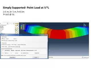
Step 13. Plot the Results Plot the results • Results: Create / Quick Plot • Select Stress Tensor for fringe result • Select Displacement, Translational for deformation result • Click Apply. -- End of workshop -- a b c d