Download
1 / 62
670 likes | 1.22k Vues
Bluetooth PANs IEEE 802.15. Bluetooth History. Harald Blaatand “Bluetooth” II King of Denmark 940-981 AC This is one of two Runic stones erected in his capital city of Jelling The stone’s inscription (“runes”) says: Harald had dark hair Harald united Denmark & Norway

E N D
Bluetooth PANs IEEE 802.15 1
Bluetooth History • Harald Blaatand “Bluetooth” II • King of Denmark 940-981 AC • This is one of two Runic stones erected in his capital city of Jelling • The stone’s inscription (“runes”) says: • Harald had dark hair • Harald united Denmark & Norway • Harald believed that devices should seamlessly communicate [wirelessly] http://en.wikipedia.org/wiki/Harald_I_of_Denmark 2
Frequency Hopping Spread Spectrum • Invented by Hedy Lamarr and George Antheil during 1941 • Hedy knew that "guided" torpedos were much more effective hitting a target. The problem was that radio-controlled torpedos could easily be jammed by the enemy. • One afternoon she realized "we're talking and changing frequencies" all the time. At that moment, the concept of frequency-hopping was born. • Antheil gave Lamarr most of the credit, but he supplied the player piano technique. Using a modified piano roll in both the torpedo and the transmitter, the changing frequencies would always be in synch. A constantly changing frequency cannot be jammed. 3
Overview • Universal short-range wireless capability • Uses 2.4-GHz band • Available globally for unlicensed users • Devices within 10 m can share up to 720 kbps of capacity • Supports open-ended list of applications • Data, audio, graphics, video 4
Bluetooth Application Areas • Data and voice access points • Real-time voice and data transmissions • Cable replacement • Eliminates need for numerous cable attachments for connection • Ad hoc networking • Device with Bluetooth radio can establish connection with another when in range 5
Bluetooth Standards Documents • Core specifications • Details of various layers of Bluetooth protocol architecture • IEEE 802.15.1 • Profile specifications • Use of Bluetooth technology to support various applications • Bluetooth consortium 7
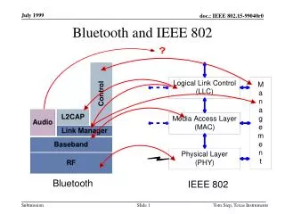
Protocol Architecture • Bluetooth has a layered protocol architecture • Core protocols • Cable replacement and telephony control protocols • Adopted protocols • Core protocols • Radio • Baseband • Link manager protocol (LMP) • Logical link control and adaptation protocol (L2CAP) • Service discovery protocol (SDP) 8
Bluetooth Protocol Technology • The following MAC procedures support the asynchronous connectionless or connection-oriented (ACL) and synchronous connection-oriented (SCO) link delivery services: • The baseband (BB) layer, specifying the lower level operations at the bit and packet levels, e.g., forward error correction (FEC) operations, encryption, cyclic redundancy check (CRC) calculations, Automatic Repeat Request (ARQ) Protocol. • The link manager (LM) layer, specifying connection establishment and release, authentication, connection and release of SCO and ACL channels, traffic scheduling, link supervision, and power management tasks. • The Logical Link Control and Adaptation Protocol (L2CAP) layer, forming an interface to standard data transport protocols. It handles the multiplexing of higher layer protocols and the segmentation and reassembly (SAR) of large packets. The data stream crosses the LM layer, where packet scheduling on the ACL channel takes place. The audio stream is directly mapped on an SCO channel and bypasses the LM layer. The LM layer, though, is involved in the establishment of the SCO link. Control messages are exchanged between the LM layer and the application. • The 2.4 GHz industrial, scientific, and medical (ISM) band PHY signaling techniques and interface functions that are controlled by the IEEE 802.15.1-2005 MAC. • Above the L2CAP layer may reside the Serial Cable Emulation Protocol based on ETSI TS 07.10 (RFCOMM), Service Discovery Protocol (SDP), Telephone Control Protocol specification (TCS), voice-quality channels for audio and telephony, and other network protocols. These protocols are necessary for interoperability for end-user products, but are outside the scope of this standard. 9
Usage Models 11
Usage Models 12
Usage Models 13
Piconets and Scatternets • Piconet • Basic unit of Bluetooth networking • Master and one to seven slave devices • Master determines channel and phase • Scatternet • Device in one piconet may exist as master or slave in another piconet • Allows many devices to share same area • Makes efficient use of bandwidth • Not implemented in COTS equipment 14
Applications TCP/IP HID RFCOMM Application Framework and Support Data Control Host Controller Interface Audio L2CAP Link Manager and L2CAP Link Manager Baseband Radio & Baseband RF Bluetooth Overview Logical Link Control & Adaptation Protocol • A hardware/software description • An application framework 16
Bluetooth CONOPS • The RF (PHY) operates in the unlicensed ISM band at 2.4 GHz. The system employs a frequency hop transceiver to combat interference and fading and provides many frequency hopping spread spectrum (FHSS) carriers. RF operation uses a shaped, binary frequency modulation to minimize transceiver complexity. The symbol rate is 1 Msymbol/s supporting the bit rate of 1 Mb/s. • During typical operation, a physical radio channel is shared by a group of devices that are synchronized to a common clock and frequency hopping pattern. One device provides the synchronization reference and is known as the master. All other devices are known as slaves. A group of devices synchronized in this fashion form a piconet. This is the fundamental form of communication in the technology. • Devices in a piconet use a specific frequency hopping pattern, which is algorithmically determined by fields in the device address and the clock of the master. The basic hopping pattern is a pseudo-random ordering of the 79 frequencies in the ISM band. The hopping pattern may be adapted to exclude a portion of the frequencies that are used by interfering devices. The adaptive hopping technique improves coexistence with static (nonhopping) ISM systems when these are collocated. • The physical channel is subdivided into time units known as slots. Data are transmitted between devices in packets, which are positioned in these slots. When circumstances permit, a number of consecutive slots may be allocated to a single packet. Frequency hopping takes place between the transmission or the reception of packets. This standard provides the effect of full duplex transmission through the use of a time-division duplex (TDD) scheme. 17
CONOPS (cont.) • Above the physical channel, there is a layering of links and channels and associated control protocols. The hierarchy of channels and links from the physical channel upwards is physical channel, physical link, logical transport, logical link, and L2CAP channel. • Within a physical channel, a physical link is formed between any two devices that transmit packets in either direction between them. In a piconet physical channel, there are restrictions on which devices may form a physical link. There is a physical link between each slave and the master. Physical links are not formed directly between the slaves in a piconet. • The physical link is used as a transport for one or more logical links that support unicast synchronous, asynchronous and isochronous traffic, and broadcast traffic. Traffic on logical links is multiplexed onto the physical link by occupying slots assigned by a scheduling function in the resource manager. • A control protocol for the BB layer and PHY is carried over logical links in addition to user data. This is the LMP. Devices that are active in a piconet have a default asynchronous connection-oriented (ACL) logical transport that is used to transport the LMP signalling. For historical reasons, this is referred to as the ACL logical transport. The default ACL logical transport is the one that is created whenever a device joins a piconet. Additional logical transports may be created to transport synchronous data streams when this is required. • The LM function uses LMP to control the operation of devices in the piconet and provide services to manage the lower architectural levels (i.e., PHY and BB). The LMP is carried only on the default ACL logical transport and the default broadcast logical transport. • Above the BB, L2CAP provides a channel-based abstraction to applications and services. It carries out segmentation and reassembly (SAR) of application data and multiplexing and demultiplexing of multiple channels over a shared logical link. L2CAP has a protocol control channel that is carried over the default ACL logical transport. Application data submitted to the L2CAP may be carried on any logical link that supports the L2CAP. 18
Radio & Modulation • frequency synthesis: frequency hopping • 2.400-2.4835 GHz • 2.402 + k MHz, k=0, …, 78 • 1,600 hops per second • conversion bits into symbols: modulation • GFSK (BT = 0.5; 0.28 < h < 0.35); • 1 MSymbols/s • transmit power • 0 dbm (up to 20dbm with power control) • receiver sensitivity • -70dBm @ 0.1% BER 19
Frequency Hopping (FH) • Resists interference and multipath effects • Provides a form of multiple access among co-located devices in different piconets • Total bandwidth divided into 1 MHz channels • FH occurs by jumping from one channel to another in pseudorandom sequence • Hopping sequence shared across entire piconet • Piconet access: • Bluetooth devices use time division duplex (TDD) • Access technique is TDMA • FH-TDD-TDMA 20
Frequency Hopping • Each frame uses a single hop frequency for its duration 21
Transmit Power • The power steps shall form a monotonic sequence, with a maximum step size of 8 dB and a minimum step size of 2 dB. • A class 1 equipment with a maximum transmit power of +20 dBm must be able to control its transmit power down to 4 dBm or less. 23
Eye Pattern • Modulation is GFSK (Gaussian Frequency Shift Keying) with a BT=0.5. • The data transmitted has a symbol rate of 1 Ms/s. 24
RECEIVER SIGNAL STRENGTH INDICATOR The RSSI measurement compares the received signal power with two threshold levels, which define the Golden Receive Power Range. The lower threshold level corresponds to a received power between -56 dBm and 6 dB above the actual sensitivity of the receiver. The upper threshold level is 20 dB above the lower threshold level to an accuracy of +/- 6 dB Optional function 25
Bluetooth Protocol • Bluetooth uses a 625 μs slotted channel. A Time-Division Duplex (TDD) scheme is used for full duplex transmission. Information is exchanged through frames. Each frame is transmitted on a different hop frequency. A frame nominally covers a single slot, but can be extended to cover up to five slots. • The Bluetooth protocol uses a combination of circuit and frame switching. • Slots can be reserved for synchronous frames. Bluetooth can support an asynchronous data channel, up to three simultaneous synchronous voice channels, or a channel which simultaneously supports asynchronous data and synchronous voice. Each voice channel supports a 64 kb/s synchronous (voice) channel in each direction. The asynchronous channel can support maximal 723.2 kb/s asymmetric (and still up to 57.6 kb/s in the return direction), or 433.9 kb/s symmetric. 26
Unconnected: Standby Standby Detach Connecting states Inquiry Page Transmit Connected Active states data AMA AMA T =2s T =0.6s T =2ms T =2ms tpcl tpcl tpcl tpcl PARK HOLD Low-power states PMA AMA releases AMA address Baseband protocol • Standby • Waiting to join a piconet • Inquire • Ask about available radios • Page • Connect to a specific radio • Connected • Actively on a piconet (master or slave) • Park/Hold • Low-power connected states 27
master SCO slave ACL 0 1 2 3 4 5 6 7 8 9 10 11 12 13 14 15 16 1718 19 20 21 22 Baseband link types • Polling-based (TDD) frame transmissions • 1 slot: 0.625msec (max 1600 slots/sec) • master/slave slots (even-/odd-numbered slots) • polling: master always “polls” slaves • Synchronous connection-oriented (SCO) link • “circuit-switched” • periodic single-slot frame assignment • symmetric 64Kbps full-duplex • Asynchronous connection-less (ACL) link • Frame switching • asymmetric bandwidth • variable frame size (1-5 slots) • max. 721 kbps (57.6 kbps return channel) • 108.8 - 432.6 kbps (symmetric) 28
Bluetooth Frame Fields • Access code • used for timing synchronization, offset compensation, paging, and inquiry • Header • used to identify frame type and carry protocol control information • Payload • contains user voice or data and payload header, if present 29
Bluetooth Frame Structure Frame ACCESS CODE - based on identity and system clock of Master Provides means for synchronization; Unique for channel; Used by all frames on the channel 30
Types of Access Codes • Channel access code (CAC) • identifies a piconet • Device access code (DAC) • used for paging and subsequent responses • Inquiry access code (IAC) • used for inquiry purposes 31
Access Code • Preamble – used for DC compensation • 0101 if LSB of sync word is 0 • 1010 if LSB of synch word is 1 • Sync word – 64-bits, derived from: • 7-bit Barker sequence • Lower address part (LAP) • Pseudonoise (PN) sequence • Trailer • 0101 if MSB of sync word is 1 • 1010 if MSB of sync word is 0 32
Bluetooth Baseband Format Frame Frame Frames 33 Frame
Frame Header Fields • AM_ADDR • contains “active mode” address of one of the slaves • Type • identifies type of frame • Flow • 1-bit flow control • ARQN • 1-bit acknowledgment • SEQN • 1-bit sequential numbering schemes • Header error control (HEC) • 8-bit error detection code 35
Payload Format • Payload header • L_CH field – identifies logical channel • Flow field – used to control flow at L2CAP level • Length field – number of bytes of data • Payload body • contains user data • CRC • 16-bit CRC code 36
Error Correction Schemes • 1/3 rate FEC (forward error correction) • Used on 18-bit frame header, voice field in HV1 frame • 2/3 rate FEC • Used in DM frames, data fields of DV frame, FHS frame and HV2 frame • ARQ • Used with DM and DH frames 38
ARQ Scheme Elements • Error detection • destination detects errors, discards frames • Positive acknowledgment • destination returns positive acknowledgment • Retransmission after timeout • source retransmits if frame is unacknowledged • Negative acknowledgment and retransmission • destination returns negative acknowledgement for errored frames, source retransmits 39
Logical Channels • Link control (LC) • Link manager (LM) • User asynchronous (UA) • User isochronous (UI) • Use synchronous (US) 42
Channel Control • States of operation of a piconet during link establishment and maintenance • Major states • Standby – default state • Connection – device connected 43
Channel Control • Interim substates for adding new slaves • Page – device issued a page (used by master) • Page scan – device is listening for a page • Master response – master receives a page response from slave • Slave response – slave responds to a page from master • Inquiry – device has issued an inquiry for identity of devices within range • Inquiry scan – device is listening for an inquiry • Inquiry response – device receives an inquiry response 45
Inquiry Procedure • Potential master identifies devices in range that wish to participate • Transmits ID frame with inquiry access code (IAC) • Occurs in Inquiry state • Device receives inquiry • Enter Inquiry Response state • Returns FHS frame with address and timing information • Moves to page scan state 46
Page Procedure • Master uses devices address to calculate a page frequency-hopping sequence • Master pages with ID frame and device access code (DAC) of specific slave • Slave responds with DAC ID frame • Master responds with its FHS frame • Slave confirms receipt with DAC ID • Slaves moves to Connection state 47
Slave Connection State Modes • Active – participates in piconet • Listens, transmits and receives frames • Sniff – only listens on specified slots • Hold – does not support ACL frames • Reduced power status • May still participate in SCO exchanges • Park – does not participate on piconet • Still retained as part of piconet 48
Bluetooth Audio • Voice encoding schemes: • Pulse code modulation (PCM) • Continuously variable slope delta (CVSD) modulation • Choice of scheme made by link manager • Negotiates most appropriate scheme for application 49
Bluetooth Link Security • Elements: • Authentication – verify claimed identity • Encryption – privacy • Key management and usage • Security algorithm parameters: • Unit address • Secret authentication key • Secret privacy key • Random number 50