Download
1 / 46
500 likes | 1.09k Vues
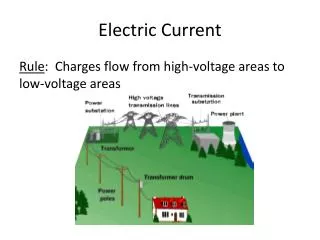
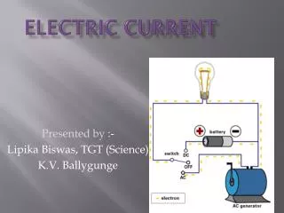
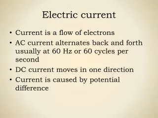
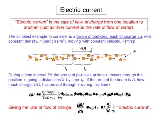
Electric Current. Definition : rate of positive charge flow Symbol : i Units : Coulombs per second ≡ Amperes (A) i = dq/dt where q = charge (in Coulombs), t = time (in seconds) Note: Current has polarity. Electric Potential (Voltage). Definition : energy per unit charge

E N D
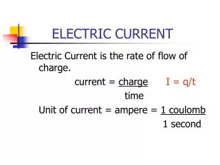
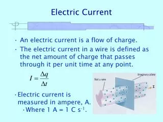
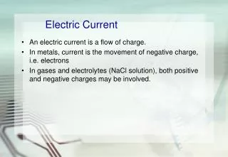
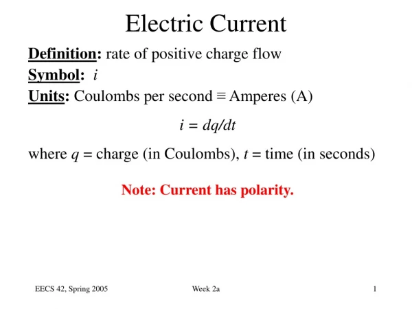
Electric Current Definition: rate of positive charge flow Symbol: i Units:Coulombs per second ≡ Amperes (A) i = dq/dt where q = charge (in Coulombs), t = time (in seconds) Note: Current has polarity. Week 2a
Electric Potential (Voltage) • Definition: energy per unit charge • Symbol: v • Units:Joules/Coulomb≡Volts (V) v = dw/dq where w = energy (in Joules), q = charge (in Coulombs) Note: Potential is always referenced to some point. a Subscript convention: vab means the potential at a minus the potential at b. vab≡ va - vb b Week 2a
Electric Power • Definition: transfer of energy per unit time • Symbol: p • Units:Joules per second ≡ Watts (W) p = dw/dt = (dw/dq)(dq/dt) = vi • Concept: As a positive charge q moves through a drop in voltage v, it loses energy • energy change = qv • rate is proportional to # charges/sec Week 2a
The Ideal Basic Circuit Element i • Polarity reference for voltage can be • indicated by plus and minus signs • Reference direction for the current • is indicated by an arrow + v _ Attributes: • Two terminals (points of connection) • Mathematically described in terms of current and/or voltage • Cannot be subdivided into other elements Week 2a
A Note about Reference Directions A problem like “Find the current” or “Find the voltage” is always accompanied by a definition of the direction: - v + i In this case, if the current turns out to be 1 mA flowing to the left, we would say i = -1 mA. In order to perform circuit analysis to determine the voltages and currents in an electric circuit, you need to specify reference directions. There is no need to guess the reference direction so that the answers come out positive, however. Week 2a
Sign Convention Example Suppose you have an unlabelled battery and you measure its voltage with a digital voltmeter (DVM). It will tell you the magnitude and sign of the voltage. With this circuit, you are measuring vab. The DVM indicates 1.401, so va is lower than vb by 1.401 V. Which is the positive battery terminal? Note that we have used the “ground” symbol ( ) for the reference node on the DVM. Often it is labeled “C” for “common.” Week 2a
Sign Convention for Power Passive sign convention p = vi p = -vi i i i i _ v + _ v + + v _ + v _ • If p > 0, power is being delivered to the box. • If p < 0, power is being extracted from the box. Week 2a
Power Calculation Example Find the power absorbed by each element: Conservation of energy total power delivered equals total power absorbed Aside: For electronics these are un- realistically large currents – mA is more typical than A p (W) vi (W) 918 - 810 - 12 - 400 - 224 1116 Week 2a
Circuit Elements • 5 ideal basic circuit elements: • voltage source • current source • resistor • inductor • capacitor • Many practical systems can be modeled with just sources and resistors • The basic analytical techniques for solving circuits with inductors and capacitors are the same as those for resistive circuits active elements, capable of generating electric energy passive elements, incapable of generating electric energy Week 2a
Electrical Sources • An electrical source is a device that is capable of converting non-electric energy to electric energy and vice versa. Examples: • battery: chemical electric • dynamo (generator/motor): mechanical electric • Electrical sources can either deliver or absorb power Week 2a
Ideal Independent and Dependent Voltage Sources • Circuit element that maintains a prescribed voltage across its terminals, regardless of the current flowing in those terminals. • Voltage is known, but current is determined by the circuit to which the source is connected. • The voltage can be either independent or dependent on a voltage or current elsewhere in the circuit, and can be constant or time-varying. Circuit symbols: vs + vs=m vx + vs=r ix + _ _ _ independent current-controlled voltage-controlled Week 2a
Other Independent Voltage Source Symbols Sinusoidal AC source v(t) = Vpeaksin(wt) Veffective = Vpeak\/2 (In US, 120 V, so Vpeak = 170 V) Battery (realistic source) + VS Week 2a
I-V Plot for a Real Battery Week 2a
Ideal Independent and Dependent Current Sources • Circuit element that maintains a prescribed current through its terminals, regardless of the voltage across those terminals. • Current is known, but voltage is determined by the circuit to which the source is connected. • The current can be either independent or dependent on a voltage or current elsewhere in the circuit, and can be constant or time-varying. Circuit symbols: is is=a vx is=b ix independent current-controlled voltage-controlled Week 2a
Electrical Resistance • Resistance: Electric field is proportional to current density, within a resistive material. Thus, voltage is proportional to current. The circuit element used to model this behavior is the resistor. Circuit symbol: Units: Volts per Ampere ≡ ohms (W) • The current flowing in the resistor is proportional to the voltage across the resistor: v = i R where v = voltage (V), i = current (A), and R = resistance (W) R (Ohm’s Law) Week 2a
Resistance of an actual resistor Material resistivity = r (W-cm) T L W Resistance = resistivity x length/(cross-sectional area) R = r (L/WT) Week 2a
Electrical Conductance • Conductance is the reciprocal of resistance. Symbol: G Units: siemens (S) or mhos ( ) Example: Consider an 8 W resistor. What is its conductance? W Week 2a
Short Circuit and Open Circuit Wire (“short circuit”): • R = 0 no voltage difference exists (all points on the wire are at the same potential) • Current can flow, as determined by the circuit Air (“open circuit”): • R = no current flows • Voltage difference can exist, as determined by the circuit Week 2a
Circuit Nodes and Loops • A node is a point where two or more circuit elements are connected. • A loop is formed by tracing a closed path in a circuit through selected basic circuit elements without passing through any intermediate node more than once Example: Week 2a
Kirchhoff’s Laws • Kirchhoff’s Current Law (KCL): • The algebraic sum of all the currents entering any node in a circuit equals zero. • Kirchhoff’s Voltage Law (KVL): • The algebraic sum of all the voltages around any loop in a circuit equals zero. Week 2a
Example: Power Absorbed by a Resistor p = vi = ( iR )i = i2R p = vi = v ( v/R ) = v2/R Note that p > 0 always, for a resistor. Example: • Calculate the voltage vg and current ia. • Determine the power dissipated in the 80W resistor. Week 2a
“Lumped Element” Circuit Modeling (Model = representation of a real system which simplifies analysis) • In circuit analysis, important characteristics are grouped together in “lumps” (separate circuit elements) connected by perfect conductors (“wires”) • An electrical system can be modeled by an electric circuit (combination of paths, each containing 1 or more circuit elements) if l = c/f >> physical dimensions of system Distance travelled by a particle travelling at the speed of light in one period Example: f = 60 Hz l = 3 x 10⁸ m/s / 60 = 5 x 10⁶ m Week 2a
Construction of a Circuit Model • The electrical behavior of each physical component is of primary interest. • We need to account for undesired as well as desired electrical effects. • Simplifying assumptions should be made wherever reasonable. Week 2a
Terminology: Nodes and Branches Node: A point where two or more circuit elements are connected Branch: A path that connects two nodes Week 2a
Notation: Node and Branch Voltages • Use one node as the reference (the “common” or “ground” node) – label it with a symbol • The voltage drop from node x to the reference node is called the node voltagevx. • The voltage across a circuit element is defined as the difference between the node voltages at its terminals Example: –v1 + a R1 b + va _ + vb _ + vs R2 _ c REFERENCE NODE Week 2a
Using Kirchhoff’s Current Law (KCL) Consider a node connecting several branches: i2 i3 i1 i4 • Use reference directions to determine whether currents are “entering” or “leaving” the node – with no concern about actual current directions Week 2a
Formulations of Kirchhoff’s Current Law (Charge stored innode is zero.) Formulation 1: Sum of currents entering node = sum of currents leaving node Formulation 2: Algebraic sum of currents entering node = 0 • Currents leaving are included with a minus sign. Formulation 3: Algebraic sum of currents leaving node = 0 • Currents entering are included with a minus sign. Week 2a
A Major Implication of KCL • KCL tells us that all of the elements in a single branch carry the same current. • We say these elements are connected in series. Current entering node = Current leaving node i1 = i2 Week 2a
KCL Example Currents entering the node: Currents leaving the node: -10 mA i 5 mA 15 mA 3 formulations of KCL: 1. 2. 3. Week 2a
Generalization of KCL • The sum of currents entering/leaving a closed surface is zero. Circuit branches can be inside this surface, i.e. the surface can enclose more than one node! i2 i3 This could be a big chunk of a circuit, e.g., a “black box” i4 i1 Week 2a
Generalized KCL Examples 50 mA 5mA i 2mA i Week 2a
Using Kirchhoff’s Voltage Law (KVL) Consider a branch which forms part of a loop: – v2 + + v1 _ voltage “drop” voltage “rise” (negative drop) loop loop • Use reference polarities to determine whether a voltage is dropped – with no concern about actual voltage polarities Week 2a
Formulations of Kirchhoff’s Voltage Law (Conservation of energy) Formulation 1: Sum of voltage drops around loop = sum of voltage rises around loop Formulation 2: Algebraic sum of voltage drops around loop = 0 • Voltage rises are included with a minus sign. Formulation 3: Algebraic sum of voltage rises around loop = 0 • Voltage drops are included with a minus sign. (Handy trick: Look at the first sign you encounter on each element when tracing the loop.) Week 2a
A Major Implication of KVL • KVL tells us that any set of elements that are connected at both ends carry the same voltage. • We say these elements are connected in parallel. + va _ + vb _ Applying KVL in the clockwise direction, starting at the top: vb – va = 0 vb = va Week 2a
v2 v3 + + 2 1 + + + va vb vc - 3 KVL Example Three closed paths: b a c Path 1: Path 2: Path 3: Week 2a
+ An Underlying Assumption of KVL • No time-varying magnetic flux through the loop Otherwise, there would be an induced voltage (Faraday’s Law) • Note: Antennas are designed to “pick up” electromagnetic waves; “regular circuits” often do so undesirably. Avoid these loops! How do we deal with antennas (EECS 117A)? Include a voltage source as the circuit representation of the induced voltage or “noise”. (Use a lumped circuit model rather than a distributed (wave) model.) Week 2a
+ Resistors in Series Consider a circuit with multiple resistors connected in series. Find their “equivalent resistance”. • KCL tells us that the same current (I) flows through every resistor • KVL tells us I R1 R2 VSS R3 R4 Equivalent resistance of resistors in series is the sum Week 2a
+ Voltage Divider I = VSS / (R1 + R2 + R3 + R4) I + – V1 R1 R2 + – VSS V3 R3 R4 Week 2a
+ + R R 2 2 V V × × V V = ≠ 2 2 SS SS R R + + R R + + R R + + R R 1 1 2 2 3 3 4 4 When can the Voltage Divider Formula be Used? I I R1 R1 + – + – R2 R2 V2 V2 VSS VSS R3 R3 R4 R4 R5 Correct, if nothing else is connected to nodes because R5 removes condition ofresistors in series Week 2a
Resistors in Parallel Consider a circuit with two resistors connected in parallel. Find their “equivalent resistance”. x • KVL tells us that the • same voltage is dropped • across each resistor • Vx = I1 R1 = I2 R2 • KCL tells us I1 I2 ISS R1 R2 Week 2a
+ + I I V eq R1 R2 R3 V Req General Formula for Parallel Resistors What single resistance Req is equivalent to three resistors in parallel? Equivalent conductance of resistors in parallel is the sum Week 2a
Current Divider x I1 I2 Vx = I1 R1 = ISS Req ISS R1 R2 Week 2a
+ V Generalized Current Divider Formula Consider a current divider circuit with >2 resistors in parallel: Week 2a