Download

1 / 25
260 likes | 761 Vues
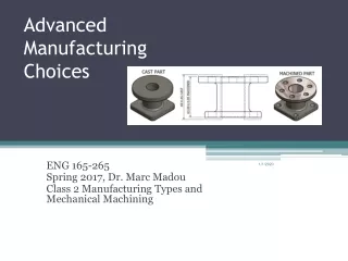
Advanced Manufacturing Choices MAE 195-MAE 165 Spring 2009, Dr. Marc Madou Class 2 Table of Content Manufacturing types: Primary, secondary and tertiary manufacturing Mechanical machining definition Recognized categories of mechanical machining: turning, milling, drilling and grinding.

E N D
Advanced Manufacturing Choices MAE 195-MAE 165 Spring 2009, Dr. Marc Madou Class 2
Table of Content • Manufacturing types: Primary, secondary and tertiary manufacturing • Mechanical machining definition • Recognized categories of mechanical machining: turning, milling, drilling and grinding. • CNC machining • Precision machining • Ultraprecision and nanotechnology • Desk top factory (DTF)
Manufacturing Types • Manufacturing dominates world trade. It is the main wealth creating activity of all industrialized nations and many developing nations. A manufacturing industry based on advanced technologies with the capability of competing in world markets can ensure a higher standard of living for an industrial nation (McKeown, 1996). • Where primary manufacturing processes involve casting* and molding**, secondary manufacturing processes constitute the main mechanical removing techniques involving turning, drilling and milling. Abrasive processes to super-finish a work-piece are called tertiary manufacturing processes. Casting*/molding**: The act or process of making casts or impressions, or of shaping metal or plaster in a mold; the act or the process of pouring molten metal into a mold.
Manufacturing Types • The difference between casting and molding is that in "traditional" casting processes, the mold is destroyed/ consumed when removing the work-piece from it while in molding, the mold is re-used multiple times(this difference is not often respected in naming different processes). • Lost wax casting process: see video • Sand casting: see utube
Mechanical Machining • In mechanical removal processes, stresses induced by a tool overcome the strength of the material. • The process produces complex 3D shapes, with very good dimensional control, and good surface finishes. • The method is wasteful of material, and expensive in terms of labor and capital. • How well a part made from a given material holds its shape with time and stress is referred to as the dimensional stability of the part and the material.
Mechanical Machining • To maximize dimensional stability, the machine design engineer tries to minimize the ratios of applied and residual stress to yield strength of the material. • A good rule of thumb is to keep the static stress below 10 to 20% of yield strength. • Increased heat at the work-piece causes uneven dimensional changes in the part being machined, making it difficult to control its dimensional accuracy and tolerances. Thermal errors are often the dominant type of error in a precision machine, and thermal characteristics such as thermal expansion coefficient and thermal conductivity deserve special attention .
Mechanical Machining • In mechanical subtractive machining, physical removal of unwanted material is achieved by mechanical energy applied at the work piece. • Mechanical material removing technologies are also categorized as single point machining or abrasive machining I.e., multi-point machining). • Mechanical removal processes can be broken down into four commonly recognized categories: turning, milling, drilling and grinding. First lathe as depicted in an Egyptian bas relief; about 300 B.C. Shown here in a line drawing. The man at left is holding the cutting tool. The man at the right is making the workpiece rotate back and forth by pulling on a cord or thong.
Mechanical Energy Based Removing • What is milling? The use of a rotating multi-point cutting tool to machine flat surfaces, slots, or internal recesses into a work-piece. • Milling is one of the more versatile machining processes. There are three degrees of freedom associated with milling. The tool can move up and down, left to right, and front to back. In this process the tool spins while the part remains stationary. Although milling is a more versatile process than turning or grinding, it is not as accurate and tends to leave a rougher surface finish than the other two processes. • What is turning ? Turning is the machining operation that produces cylindrical parts. In its basic form, it can be defined as the machining of an external surface with the work-piece rotating and with a single-point cutting tool.
Mechanical Energy Based Removing • The main difference between turning and milling is that in turning the work-piece spins while the tool remains stationary. Because of this, turning can be used to create a great surface finish on cylindrical parts. • Turning is done on a machine called a lathe. The lathe spins the workpiece, while the lathe operator can position the tool to remove the material. The work-piece is held in the chucks of the lathe.
Mechanical Energy Based Removing • Drilling can be defined as a rotary end cutting tool having one or more cutting lips, and having one or more helical or straight flutes for the passage of chips and the admission of a cutting fluid.
Mechanical Energy Based Removing • Grinding is a finishing process that is used to remove surplus material from the work-piece surface. It is usually used on almost any surface that has been previously rough machined and is among the most expensive process for it is generally quite slow in removing material.
Mechanical Energy Based Removing • By 1977, highly precise instruments such as servomotors, feedback devices, and computers were implemented, paving the way for computer numerical control machining, commonly called CNC machining, which is now standard in many types of machine shops. At the start, the smallest movement these machines could reproducibly make was 0.5 µm. • The resolution of the steps a machine can make, of course, is a determining factor for the manufacturing accuracy of the work-piece. • Numerical control is a method of automatically operating a manufacturing machine based on a code of letters, numbers, and special characters.
Mechanical Energy Based Removing • Point-to-point control systems cause the tool to move to a point on the part and execute an operation at that point only. The tool is not in continuous contact with the part while it is moving. • Continuous-path controllers cause the tool to maintain continuous contact with the part as the tool cuts a contour shape.
Mechanical Energy Based Removing • These continuous operations include milling along any lines at any angle, milling arcs and lathe turning.
Right hand rule Vertical milling machine Mechanical Energy Based Removing • CNC machines milling machines can perform simultaneous linear motion along the three axis and are called three-axes machines. • More complex CNC machines have the capability of executing additional rotary motions (4th and 5th axes).
Mechanical Energy Based Removing • Machining Centers, equipped with automatic tool changers, are capable of changing 90 or more tools. Can perform milling, drilling,boring* turning, … on many faces. * Boring is the process of using a single-point tool to enlarge a preexisting hole. • Process flow: • Develop or obtain the 3D geometric model of the part, using CAD. • Decide which machining operations and cutter-path directions are required (computer assisted). • Choose the tooling required (computer assisted). • Run CAM software to generate the CNC part program. • Verify and edit program. • Download the part program to the appropriate machine. • Verify the program on the actual machine and edit if necessary.Run the program and produce the part.
Mechanical Energy Based Removing • In an integrated CAD/CAM system, the geometry and tool motions are derived automatically from the CAD database by the NC program (Pro/E, Unigraphics, ….) CNC milling is a cutting process in which material is removed from a block of material by a rotating tool using computer numerically controlled program or code to achieve a desired tool path to machine very accurate parts precisely and efficiently.
Precision Machining • Mechanical engineers define precision machining as machining in which the relative accuracy (tolerance/object size) is 10–4 or less of a feature/part size • For comparison, a relative accuracy of 10–3 in the construction of a house is considered excellent. It is important to realize that, while IC techniques and silicon micro- and nano-machining can achieve excellent absolute tolerances, relative tolerances here are rather poor compared to those achieved by most mechanical machining techniques. • The decrease in manufacturing accuracy with decreasing size is rarely mentioned in discussions of Si micro-machines; this probably is because Si micromachining originated from electrical engineering practice rather than mechanical engineering.
Precision Machining • In the 1980s advanced machine tools became equipped with precision metrology and control tools. These machines used laser interferometer and capacitance probe feedback controls, temperature control and hydrostatic bearings, and featured accuracies better than 0.1 micrometers. Precision manufacturing methods were extended for industrial use for cutting aluminum, which was used for making components for scanners, photocopying machines and computer memory disks. Also in the 1980s, cutting with very small diamond tools (e.g., 22 µm diameter) was developed in Japan.
Ultra Precision Machining-Nanotechnology • Taniguchi coined the term nanotechnology and in 1974, used the term to define ultra-precision machining. • Taniguchi defines ultra-precision machining as “the process by which the highest possible dimensional accuracy is achieved at a given point in time.” • See Norio Taniguchi predicted accuracies along with the processes or tools used to achieve it (next page) Norio Taniguchi (谷口紀男) (27 May1912 - 15 November1999) was a professor of Tokyo Science University.
Ultra Precision Machining-Nanotechnology • By 1993, 0.05 µm became possible, and today there is equipment available featuring 0.01 µm and even nanometer step resolution 10 (http://www.fanuc.co.jp/eindex.htm). • This evolution closely follows the predictions sketched in the Taniguchi curves showing a machining accuracy for ultra-precision machining of sub-nanometer resolution for the year 2008 (see previous slide) . • Fanuc’s the ROBOnano Ui an ultra-precision micromachining station (cost 1 $ million) and a Noh mask made with this machine (http://www.fanuc.co.jp/en/product/robonano/index.htm).
Desk top factory • The fact that it often takes a two-ton machine tool to fabricate micro parts, where cutting forces are in the milli- to micro-Newton range is a clear indication that a complete machine tool redesign is required for the fabrication of micro-machines. • One approach is the desk-top factory.
Desk top factory • Desktop factories (DTF) constitute a rather interesting new manufacturing philosophy involving flexible and modular table-top-sized automated factories that feature minimal human participation in the manufacturing process. • An example of such a factory is shown below. Since the early nineties progress has been made towards making such desktop factories (DTF) a reality. A desktop factory as shown here has the potential of becoming the factory of the future: a totally self-contained, robotic, desktop-size machine tool that only requires materials, power and water as outside inputs, and out come the finished machined products. The first R&D desktop factories incorporated lathes, cleaning, gluing, punching and drilling stations. The workpiece is transported between these different machining functions by a “cart” moving from station to station.
Desk top factory • An example of a desktop factory at AIST, Japan.