Download
1 / 47
480 likes | 615 Vues
Chapter 8 LAN Architectures. Part II: Understanding Internet Access Technologies. Topics Addressed in Chapter 8. What is meant by LAN architecture? LAN topologies Data link and media access control protocols Physical layer data encoding in LANs Ethernet architectures Token ring LANs

E N D
Chapter 8LAN Architectures Part II: Understanding Internet Access Technologies
Topics Addressed in Chapter 8 • What is meant by LAN architecture? • LAN topologies • Data link and media access control protocols • Physical layer data encoding in LANs • Ethernet architectures • Token ring LANs • FDDI and 100VG-AnyLAN • ATM LANs • Virtual LANs • Wireless LAN architectures • LAN architecture selection criteria • IEEE LAN standards
What is Meant By LAN Architecture? • LAN architecture is the overall design of a LAN. It includes: • LAN hardware • LAN software • LAN topology • Media access control (MAC) protocol • The LAN’s network operating system is sometimes also considered to be part of LAN architecture
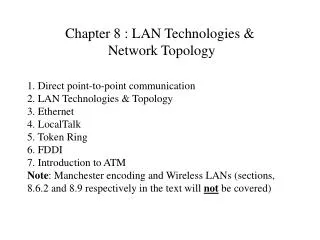
LAN Topologies • There are two types of LAN topologies: physical and logical • Physical LAN topology refers to the physical layout of the network • The way in which the communication is configured and how nodes attach to the network • Because the focus is on physical connections among hardware component, physical topologies correspond to the physical layer of the OSI reference model • Logical topology is concerned with how messages are passed from node to node within the network
Physical Topologies • LAN’s have three basic physical topologies: • Bus: all nodes attach to a common communication pathway or channel • Ring: the medium forms a loop to which all nodes are attached • Star: uses a central station (hub or switch) to which all other nodes have point-to-point connections; all communication among nodes occurs through this central station • These are illustrated in Figure 8-1 • Physical star topologies are most common in today’s LANs
Bus Topologies • In a classic bus topology, the medium consists of a single wire or cable to which other nodes are attached via connectors or transceivers • Variations include a primary bus with spurs (see Figure 8-2) • Disadvantages include the potential for loose connections or breaks in the bus to disrupt the entire network • Early Ethernet LAN implementations were typically physical bus architectures; today, most Ethernet implementations are physical stars • However, an Ethernet shared media hub is sometimes called a “bus in a box” • Both IEEE 802.3 standard and IEEE 802.4 standards and their protocols address communication over LANs with bus topologies
Ring Topologies • In a physical ring topology, the communication medium forms a closed loop (ring) and all stations are connected to the loop • Data is transmitted node-to-node in one direction on the ring (see Figure 8-3) • Similar to a linear bus, the entire network could be disrupted if one of the connectors or links in the ring should fail • Physical ring topologies are less common than bus or star topologies • Token ring and FDDI LANs have physical ring topologies
IEEE 802.5 and 802.6 LANs • The most widely used microcomputer ring network is the token passing ring. It conforms to the IEEE 802.5 standard • Token ring networks physically look like a star topology, but technically they are physical rings • Token ring nodes attach to multistation access units (MAUs) – see Figure 8-4 • MAUs can be described as “a ring in a box”, because nodes attach to the physical ring by connecting to the MAU (see Figure 8-5) • MAUs can be interconnected to form larger rings (see Figure 8-6) • IEEE 802.6 addresses dual-ring metropolitan area network (MAN) architectures (see Figures 8-24 and 8-25)
Star Topologies • In LANs with star topologies, all nodes are connected to some kind of wiring center such as a hub or switch (see Figure 8-7) • Today, most LAN implementations physically resemble star topologies • Each node is isolated on its own network segment in a physical star topology which minimizes the possibility of total network disruption by a malfunctioning connector, NIC, or link • However, the network is vulnerable to wiring center failure • The use of central connection points also facilitates network traffic monitoring and network management, including network security management • ARCnet was one of the first LAN architectures with a star topology (see Figure 8-8b)
Logical Topologies • Every LAN has both a physical and logical topology • A LAN’s logical topology specifies how messages are passed from node to node within the network • It corresponds to the media access control (MAC) protocol used in the LAN • Two logical LAN topologies exist: • Sequential (or logical ring): data is passed from one node to another in a ring-like sequence • Token passing in token ring and FDDI LANs are examples • Broadcast: nodes transmit frames/packets to all other nodes in the network; only the intended recipient processes the entire frame/packet • Ethernet LANs use a logical broadcast topology
Data Link Protocols • Data link protocols, including those used in LANs, are responsible for establishing the rules by which nodes gain access to a network’s communication medium and exchange messages. Such protocols describe several important aspects of the message exchange process including: • Delineation of data • Error control • Addressing • Transparency • Code independence • Media access--this is governed by media access control (MAC) protocols
LLC and MAC Sublayers • LANs employ two primary data link protocols: contention and token passing • In IEEE 802 standards, the data link layer is divided into two sublayers LLC and MAC (see Figure 8-10) • LLC (logical link control) is responsible for flow control, message sequencing, message acknowledgement, and error checking • MAC (media access control) enables network nodes to access the communication medium via contention or token passing
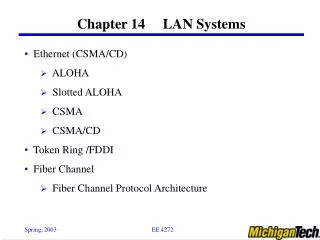
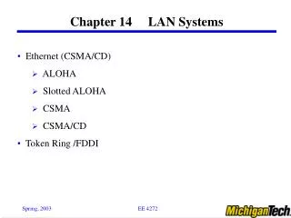
CSMA/CD • CSMA/CD (Carrier Sense Multiple Access and Collision Detection) is most widely used contention-based MAC used in LANs • It is the MAC protocol used in Ethernet LANs • In a true contention MAC (like CSMA/CD), each node has equal access to the medium • As noted in Table 8-1, each node monitors the medium for data traffic and if none is detected, it begins transmitting data • A collision occurs when two or more nodes begin to transmit at the same time • To avoid collision recurrence, each node waits a random time interval (hardwired in its NIC) before attempting to retransmit
CSMA/CA • CSMA/CA (Carrier Sense Multiple Access and Collision Avoidance) is a variation of CSMA/CD used in wireless LANs because it is difficult to detect collisions in such networks • When CSMA/CA is used, each node must wait a random time interval (hardwired in the wireless NIC) after detecting a clear medium before transmitting
Token Passing • Token passing is the other major MAC protocol found in LANs • It is used in token ring and FDDI LANs and other networks with logical ring topologies • The token is a pre-defined bit pattern that is passed among network attached computers until one of them wants to use the medium to transmit data • Token passing is summarized in Table 8-2 • In token ring networks that resemble physical star topologies, token passing takes place within MAUs (see Figure 8-12) • Token passing can be used in bus topologies as well as in physical ring topologies (see Figure 8-11) • Table 8-3 compares token passing and CSMA/CD
Physical Layer Data Encoding • Baseband transmission is common in LANs • When LAN nodes use the communication medium, their NICs transmit digital signals to represent the bits in data link layer protocols frames directly onto the medium • Some of the encoding schemes used in LANs are illustrated in Figure 8-13. These include: • Manchester encoding (used in 10 mbps Ethernet) • 4B5B (used in 100 mbps Ethernet) • Differential Manchester encoding (used in token ring LANs) • NRZI (used in FDDI LANs)
Ethernet LAN Architectures • IEEE 802.3-compliant LANs are better known as Ethernet LANs • There are a variety of IEEE 802.3-compliant LANs (see Table 8-4) • Today, most Ethernet LANs have physical star topologies; some have physical bus topologies • All Ethernet LANs have broadcast logical topologies and use CSMA/CD as the MAC protocol • Figure 8-9 illustrates widely used Ethernet frame formats
Some Key Ethernet Implementations • Particularly important Ethernet implementations include: • Fast Ethernet (e.g. 100BaseT and 100BaseFX) • The IEEE 802.3u specification covers Fast Ethernet • Gigabit Ethernet (e.g. 1000BaseT, 1000BaseSX, and 1000BaseLX) • The IEEE 802.3z specification addresses Gigabit Ethernet • Iso-Ethernet enables Ethernet LANs at different geographic locations to be connected over ISDN (see Figure 8-14) • IEEE 802.9a addresses Isochronous Ethernet
Token Ring Architectures • Token ring networks are addressed in the IEEE 802.5 specification • Physically, token ring LANs resemble star topologies, but technically they are rings • Ring is physically implemented in MAUs • UTP is the most common cabling • Speed is typically 16 mbps, however, 4 mbps and 100 mbps token ring networks exist • IEEE 802.5 frame formats are illustrated in Figure 8-15
FDDI LANs • Fiber Distributed Data Interface (FDDI) was first recognized in ANSI’s X3T9.5 specification • Physically, it has a dual ring topology • It has a sequential/ring logical topology and uses a variation of token passing as the MAC protocol • Key FDDI technologies are identified in Figure 8-16 • These include single attached stations (SAS),dual attached stations (DAS), FDDI concentrators, and FDDI/Ethernet bridges • FDDI is often used as a backbone network architecture (see Figure 8-18)
100VG-AnyLAN • 100VG-AnyLAN (aka 100BaseVG) is capable of transporting both IEEE 802.3 and IEEE 802.5 frames • It provides a mechanism for interconnecting 100 mbps token ring and 100BaseT Ethernet LANs via specialized hubs and routers (see Figure 8-20) • 100VG-AnyLAN-compliant adapters are also needed • It uses demand priority access (DPA) rather than CSMA/CD as the MAC protocol in order to enable real-time voice and video frames to be given priority over other data frames
ATM LANs • ATM (asynchronous transfer mode) is a switched network architecture that employs 53-octet cells to transmit data • Two data link layers are defined: • ATM adaptation layer (AAL) • ATM • ATM physical topologies are stars • ATM NICs with 25 speeds of 25, 100, or 155 mbps are available for workstations • Ethernet and token ring LANs can interface with an organization’s ATM backbone network via ATM gateway/access switches (see Figure 8-21)
Wireless LAN Architectures • IEEE 802.11x standards are the most important wireless LAN (WLAN) specifications that exist today (see Table 8-6) • WLANs are typically implemented as physical stars • Nodes connect to wireless hubs called access points • CSMA/CA is the MAC protocol for IEEE 802.11-compliant LANs • IEEE 802.11 addresses FHSS (frequency hopping spread spectrum), DSSS (direct sequence spread spectrum), and diffuse infrared transmission • User “roaming” capabilities are also addressed • WiFi (Wireless Fidelity) certification has been developed to promote interoperability among WLAN products • The WISPR (Wireless ISP Roaming) standard is designed to enable users to roam from one publicly accessible WLAN to another
Choosing Among LAN Architectures • A number of factors should be considered when selecting among LAN architectures • Some of the major factors are described in Table 8-7; others are described in Table 8-10) • Especially important factors to consider include: • Immediate and recurring LAN costs (see Table 8-8) • Total cost of ownership (TCO) • Number of concurrent users that can be supported • Transmission speed and data throughput • Vendor support • Manageability • Scalability/expandability • Security • Adherence to widely accepted standards
802.1 High-Level Interface 802.2 Logical Link Control 802.3 CSMA/CD 802.4 Token Bus 802.5 Token Ring 802.6 Metropolitan Area Networks (MANs) 802.7 Broadband Technical Advisory Group 802.8 Fiber Optic Technical Advisory Group 802.9 Integrated Data and Voice Networks 802.10 LAN Security 802.11 Wireless LANs 802.12 Demand Priority Access Method IEEE LAN Standards & Committees
Chapter 8LAN Architectures Part II: Understanding Internet Access Technologies