Download
1 / 71
710 likes | 722 Vues
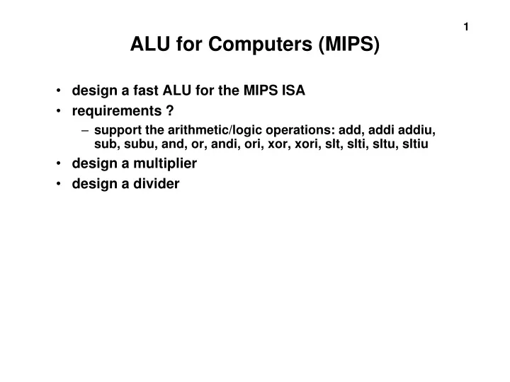
ALU for Computers (MIPS). design a fast ALU for the MIPS ISA requirements ? support the arithmetic/logic operations: add, addi addiu, sub, subu, and, or, andi, ori, xor, xori, slt, slti, sltu, sltiu design a multiplier design a divider. Review Digital Logic. Gates:. Combinational Logic.

E N D
ALU for Computers (MIPS) • design a fast ALU for the MIPS ISA • requirements ? • support the arithmetic/logic operations: add, addi addiu, sub, subu, and, or, andi, ori, xor, xori, slt, slti, sltu, sltiu • design a multiplier • design a divider
Review Digital Logic Gates: Combinational Logic
Review Digital Logic PLA: AND array, OR array
A D latch implemented with NOR gates. A D flip-flop with a falling-edge trigger.
D Q CLK Review Digital Logic Value of D is sampled on positive clock edge. Q outputssampledvalue for rest of cycle. D Q
Review: Edge-Triggering in Verilog module ff(D, Q, CLK); input D, CLK; output Q; always @ (CLK) Q <= D; endmodule Module code has two bugs. Where? module ff(D, Q, CLK); input D, CLK; output Q; reg Q; always @ (posedge CLK) Q <= D; endmodule Correct ?
R (red) Y (yellow) G (green) R Y G 1 0 0 Rst CLK Change If Change == 1 on positive CLK edge traffic light changes If Rst == 1 on positive CLK edge R Y G = 1 0 0
Rst == 1 Change == 1 R Y G R Y G R Y G 1 0 0 0 0 1 0 1 0 Change == 1 Change == 1
Rst == 1 Change == 1 R Y G R Y G R Y G 1 0 0 0 0 1 0 1 0 Change == 1 Change == 1 1 0 0 0 0 1 0 1 0 1 0 0 Change R Y G
Rst == 1 Change == 1 R Y G R Y G R Y G 1 0 0 0 0 1 0 1 0 Change == 1 Change == 1 R G D Q Y D Q D Q “One-Hot Encoding”
Rst == 1 Change == 1 R Y G R Y G R Y G 1 0 0 0 0 1 0 1 0 Change == 1 Change == 1 Rst Change Next State Combinational Logic D Q D Q D Q R G Y
R G D Q Y D Q D Q State Elements: Traffic Light Controller wire next_R, next_Y, next_G; output R, Y, G; ???
D Q CLK Value of D is sampled on positive clock edge. Q outputssampledvalue for rest of cycle. module ff(Q, D, CLK); input D, CLK; output Q; reg Q; always @ (posedge CLK) Q <= D; endmodule
R G D Q Y D Q D Q State Elements: Traffic Light Controller wire next_R, next_Y, next_G; output R, Y, G; ff ff_R(R, next_R, CLK); ff ff_Y(Y, next_Y, CLK); ff ff_G(G, next_G, CLK);
Rst Change next_R R next_G G next_Y Y Next State Logic: Traffic Light Controller Next State Combinational Logic wire next_R, next_Y, next_G; assign next_R = rst ? 1’b1 : (change ? G : R); assign next_Y = rst ? 1’b0 : (change ? R : Y); assign next_G = rst ? 1’b0 : (change ? Y : G);
wire next_R, next_Y, next_G; output R, Y, G; assign next_R = rst ? 1’b1 : (change ? G : R); assign next_Y = rst ? 1’b0 : (change ? R : Y); assign next_G = rst ? 1’b0 : (change ? Y : G); ff ff_R(R, next_R, CLK); ff ff_Y(Y, next_Y, CLK); ff ff_G(G, next_G, CLK);
Rst == 1 Change == 1 R Y G R Y G R Y G 1 0 0 0 0 1 0 1 0 Change == 1 Change == 1 Next State Combinational Logic D Q D Q D Q Logic Diagram: Traffic Light Controller R G Y
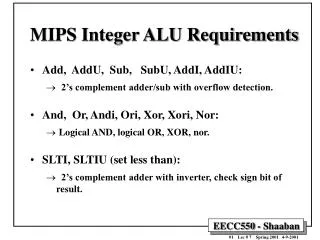
ALU for MIPS ISA • design a 1-bit ALU using AND gate, OR gate, a full adder, and a mux
ALU for MIPS ISA • design a 32-bit ALU by cascading 32 1-bit ALUs
ALU for MIPS • a 1-bit ALU performing AND, OR, addition and subtraction If we set Binvert = Carryin =1 then we can perform a - b
ALU for MIPS • include a “less” input for set-on-less-than (slt)
ALU for MIPS • design the most significant bit ALU • most significant bit need to do more work (detect overflow and MSB can be used for slt ) • how to detect an overflow overflow = carryin{MSB} xor carryout{MSB] overflow = 1 ; means overflow overflow = 0 ; means no overflow • set-on-less-than slt $1, $2, $3; if $2 < $3 then $1 = 1, else $1 = 0 ; if MSB of $2 - $3 is 1, then $1 = 1 ; 2’s comp. MSB of a negative no. is 1
ALU for MIPS • a 1-bit ALU for the MSB Overflow =Carryin XOR Carryout
A 32-bit ALU constructed from 32 1-bit ALUs
A 32-bit ALU with zero detector
ALU for MIPS • Critical path of 32-bit ripple carry adder is 32 x carry propagation delay • How to solve this problem • design trick : use more hardware • design trick : look ahead, peek • carry look adder (CLA) • CLA a b cout 0 0 0 nothing happen 0 1 cin propagate cin 1 0 cin propagate cin 1 1 1 generate propagate = a + b; generate = ab
ALU for MIPS • CLA using 4-bit as an example • two 4-bit numbers: a3a2a1a0, b3b2b1b0 • p0 = a0 + b0; g0 = a0b0 c1 = g0 + p0c0 c2 = g1 + p1c1 c3 = g2 + p2c2 c4 = g3 + p3c3 • larger CLA adders can be constructed by cascading 4-bit CLA adders • other adders: carry select adder, carry skip adder
Design Process • Divide and Conquer • using simple components • glue simple components together • work on the things you know how to do. The unknown will become obvious as you make progress • Successive Refinement • multiplier design • divider design
Multiplier • paper and pencil method multiplicand 0110 multiplier 1001 0110 0000 0000 0110 0110110 product n bits x m bits = m+n bits binary : 0 place 0 1 place a copy of multiplicand
Multiply Hardware Version 1 32 bits x 32 bits; using 64-bit multiplicand reg. 64 bit ALU, 64 bit product reg. 32 bit multiplier multiplicand shift left 64 bits shift right 64-bit ALU multiplier product write control ADD 64 bits Check the right most bit of M’r to decide to add 0 or multiplicand Control provides four control signals
Multiply Algorithm Version 1 1. test multiplier0 (i.e., bit0 of multiplier) 1.a if multiplier0 = 1, add multiplicand to product and place result in product register 2. shift the multiplicand left 1 bit 3. shift the multiplier right 1 bit 4. 32nd repetition ? if yes done if no go to 1.
Multiply Algorithm Version 1 Example 0010 x 0101 = 0000 1010 iter. step multiplier multiplicand product 0 initial 0101 0000 0010 0000 0000 1 1.a 0101 0000 0010 0000 0010 2 0101 0000 0100 0000 0010 3 0010 0000 0100 0000 0010 2 2 0010 0000 1000 0000 0010 3 0001 0000 1000 0000 0010 3 1.a 0001 0000 1000 0000 1010 2 0001 0001 0000 0000 1010 3 0000 0001 0000 0000 1010 4 2 0000 0010 0000 0000 1010 3 0000 0010 0000 0000 1010
Multiplier Algorithm Version 1 • observations from version 1 • 1/2 bits in multiplicand always 0 • use 64-bit adder is wasted (for 32 bit x 32 bit) • 0’s inserted into multiplicand as shifted left, least significant bits of the product does not change once formed • 3 steps per bit • shift product to right instead of shifting multiplicand to left ? (by adding to the left half of the product register)
Multiply Hardware Version 2 32-bit multiplicand reg. 32-bit ALU, 64-bit product reg. 32-bit multiplier reg multiplicand 32 bits shift right 32-bit ALU multiplier product shift right control ADD 32 bits 32 bits write Check the right most bit of M’r to decide to add 0 or multiplicand Write into the left half of the product register
Multiply Algorithm Version 2 1. test multiplier0 (i.e., bit 0 of the multiplier) 1a. if multiplier0 = 1 add multiplicand to the left half of product and place the result in the left half of product register; 2. shift product reg. right 1 bit 3. shift multiplier reg. right 1 bit 4. 32nd repetition ? if yes done if no, go to 1.
Multiply Algorithm Version 2 Example iter. step multiplier multiplicand product 0 initial 0011 0010 0000 0000 1 1.a 0011 0010 0010 0000 2 0011 0010 0001 0000 3 0001 0010 0001 0000 2 1.a 0001 0010 0011 0000 2 0001 0010 0001 1000 3 0000 0010 0001 1000 3 2 0000 0010 0000 1100 3 0000 0010 0000 1100 4 2 0000 0010 0000 0110 3 0000 0010 0000 0110
Multiply Version 2 • Observations • product reg. wastes space that exactly matches the size of multiplier • 3 steps per bit • combine multiplier register and product register
Multiply Hardware Version 3 • 32-bit multiplicand register, 32-bit ALU, 64-bit product register, multiplier reg is part of product register multiplicand ADD 32 bit ALU write into left half control product (multiplier) shift right
Multiply Algorithm Version 3 1. test product0 (multiplier is in the right half of product register) 1a. if product0 = 1 add multiplicand to the left half of product and place the result in the left half of product register 2. shift product register right 1 bit 3. 32nd repetition ? if yes, done if no, go to 1.
Multiply Algorithm Version 3 Example 1110 x 1011 iter. step multiplicand product 0 initial 1110 0000 1011 1 1.a 1110 1110 1011 2 1110 0111 0101 2 1.a 1110 1 0101 0101 2 1110 1010 1010 3 2 1110 0101 0101 4 1.a 1110 1 0011 0101 2 1110 1001 1010 need to save the carry 1110 x 1011 = 1001 1010 14 x 11 = 154
Multiply Algorithm Version 3 • Observations • 2 steps per bit because of multiplier and product in one register, shift right 1 bit once (rather than twice in version 1 and version 2) • MIPS registers Hi and Li correspond to left and right half of product • MIPS has instruction multu • How about signed numbers in multiplication ? • method 1: keep the sign of both numbers and use the magnitude for multiplication, after 32 repetitions, then change the product to appropriate sign. • method 2: Booth’s algorithm • Booth’s algorithm is more elegant in signed number multiplications • Booth’s algorithm uses the same hardware as version 3
Booth’s Algorithm • Motivation for Booth’s Algorithm is speed example 2 x 6 = 0010 x 0110 normal approach Booth’s approach 0010 0010 0110 0110 Booth’s approach : replace a string of 1s in multiplier by two actions action 1: beginning of a string of 1s, subtract multiplicand action 2: end of a string of 1s, add multiplicand
Booth’s Algorithm end of run middle of run beginning of run 011111111111111111110 current bit bit to the right explanation action (previous bit) 1 0 beginning of a run of 1s sub. mult’d from left half of product 1 1 middle of a run no arithmetic oper. 0 1 end of a run add mul’d to left half of product 0 0 middle of a run of 0s no arith. operation.
Booth’s Algorithm Example -2 x 7=-14 in signed binary 1110 x 0111 = 1111 0010 previous bit iteration step multiplicand product 0 initial 1110 0000 0111 0 1 sub. 1110 0010 0111 0 product shift right 1110 0001 0011 1 2 shift right 1110 0000 1001 1 3 shift right 1110 0000 0100 1 4 add 1110 1110 0100 1 shift right 1110 1111 0010 0 To begin with we put multiplier at the right half of the product register
Divide Algorithm Paper and pencil quotient divisor dividend remainder (modulo ) 1011 1010101010
Divide Hardware Version 1 • 64-bit divisor reg., 64-bit ALU, 32-bit quotient reg. 64-bit remainder register divisor shift right 64-bit ALU quotient shift left remainder write control put the dividend in the remainder register initially