Download
1 / 16
160 likes | 402 Vues
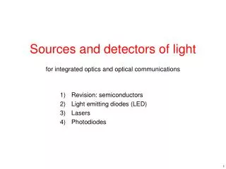
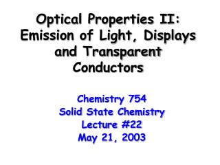
Optical Properties II: Emission of Light, Displays and Transparent Conductors. Chemistry 754 Solid State Chemistry Lecture #22 May 21, 2003. Emission of Light. The optical properties of extended solids are utilized not only for their color, but also for the way in which they emit light.

E N D
Optical Properties II:Emission of Light, Displays and Transparent Conductors Chemistry 754 Solid State Chemistry Lecture #22 May 21, 2003
Emission of Light • The optical properties of extended solids are utilized not only for their color, but also for the way in which they emit light. • Luminescence – Emission of light by a material as a consequence of it absorbing energy. There are two categories: • Fluorescence: Emission involves a spin allowed transition (short excited state lifetime) • Phosphorescence: Emission involves a spin forbidden transition (long lived excited state). • Luminescence can also be classified according to the method of excitation: • Photoluminescence: Photon excitation (i.e. fluorescent lights) • Cathodoluminescence: Cathode rays (TV & Computer displays) • Electroluminescence: Electrical injection of carriers (LED’s)
Absorbed photon Activator Emitted photon Sensitizer Energy Transfer Sensitizers and Activators • Sensitizer – Absorbs the incident energy (photon or excited electron). Often times the host lattice acts as the sensitizer. • Activator – The site where the electron radiatively relaxes. Some common ions which act as activators: • Host Lattice –Typically, the host lattice should have the following properties: • Large Band Gap – So as not to absorb the emitted radiation. • Stiff – Easily excited lattice vibrations can lead to non-radiative relaxation, which decreases the efficiency.
Common Luminescent Ions *The energy of transitions involving d, p or s orbitals is very sensitive to the crystal field splitting induced by the lattice.
Conventional Fluorescent Lights • Excitation Source • Hg gas discharge – UV Light (photoluminescence) • Sensitizer/Host Lattice • Fluoroapatite – Ca5(PO4)3F • Activators • Blue = Sb3+ (5s15p1 5s2) lmax = 480 nm • Orange-Red = Mn2+ (t2g4eg1 t2g3eg2) lmax = 580 nm
Tricolor Fluorescent Lights • Tricolor fluorescent lights are more commonly used today because they give off warmer light, due to more efficient luminescence in the red region of the spectrum. Such lights contain a blend of at least three phosphors. • Red Phosphor • Host Lattice = (Y2-xEux)O3 x = 0.06-0.10 (Bixbyite structure) • Sensitizer = O2- 2p Eu3+ 5d charge transfer (lmax ~ 230 nm) • Activator =5D07F2 transition on Eu3+[f6 ion] (lmax ~ 611 nm) • Green Phosphor • Host Lattice = (La0.6Ce0.27Tb0.13)PO4 (Monazite structure) • Sensitizer = 4f1 5d1 excitation on Ce3+ [f1 ion] (lmax ~ 250 nm) • Activator =5D47F5 transition on Tb3+ [f8 ion] (lmax~ 543 nm) • Blue Phosphor • Host Lattice = (Sr,Ba,Ca)5(PO4)3Cl (Halophosphate structure) • Sensitizer = 4f75d0 4f65d1 transition on Eu2+ • Activator =4f65d1 4f75d0 transition on Eu2+ (lmax~ 450 nm) • For a detailed yet very readable description of fluorescent light phosphors see: • http://www.electrochem.org/publications/interface/summer98/IF6-98-Page28-31.pdf
Cathode Ray Tube • The cathode ray tube is the technology used in most computer monitors and TV’s. The details of a typical commercial CRT’s are as follows. • Excitation Source • Electron beam (cathodoluminescence) • Red • Sensitizer/Host - YVO4 • Activator – Eu3+ • Green • Sensitizer/Host – ZnS (CB) • Activator – Ag+ • Blue • Sensitizer/Host – ZnS (CB) • Activator – Cu+ Image taken from http://www.howstuffworks.com/tv2.htm
Luminscence in ZnS Conduction Band • While the insulating red phosphor (Y1-xEux)VO4 operates on a principle very similar to fluorescent light phosphors (with a different excitation source of course), the blue and green phosphors employ a different scheme for electronic excitation and luminescence. • The electronic excitation in ZnS (Eg = 3.6 eV) is from the valence band to the conduction band. While the relaxation that leads to the luminescence is from the conduction band to an impurity level in the band gap. Typically either Ag+ or Cu+, which are substitutional impurities. The energy of the emitted light can be tuned by changing impurities or changing the band gap of the semiconductor. hn e- e- hn Ag+ Cu+ Valence Band
ElectroluminescenceFlat Panel Displays • Taken from the Planar systems website. • http://www.planar.com/technology/el.asp In electroluminescence an electron is directly injected into the phosphor (in the excited state) and it relaxes giving off a photon. This diagram shows how by running current through a single row (absorbant back electrode) and a single column (transparent front electrode) it is possible to light up a single pixel.
t2g eg hn O 2p t2g hn eg O 2p Self Luminescence in AWO4 • The AWO4 (A= Ca, Sr, Ba) tungstates, based upon the scheelite structure with isolated tetrahedra, are self luminescent. Luminescence in these materials can be described by the following process. • 1. WO42- group absorbs a UV photon via a charge transfer from oxygen to tungsten. • 2. Excited state electron is in an antibonding state, weakens/lengthens the bond lowering the energy of the excited state. • 3. Electron returns to the ground state giving off a longer wavelength photon.
Solid State Lasers • A Laser gives off light at a single wavelength. To achieve this the activator needs to have the following properties • A long lived excited state • A very narrow emission spectrum (localized luminescence centers) • Ruby laser • Host = Al2O3 • Activator = Cr3+ • Lifetime = 5 ms • l = 693.4 nm • Nd:YAG laser • Host = Y3Al5O12 (Garnet) • Activator = Nd3+(4f3) • Lifetime = 10-4 s • l = 1064 nm
Transparent Conducting Oxides • Characteristics of a transparent conducting oxide (TCO) • High transparency in the visible (Eg > 3.0 eV) • High electrical conductivity (s > 103 S/cm) • Applications of transparent conductors • Optoelectronic devices (LED’s, Semiconductor lasers, photovoltaic cells, etc.) • Flat Panel Displays (liquid crystals, electroluminescent displays) • Heat efficient windows (reflect IR, transparent to visible light) • Smart windows and displays based on electrochromics • Defrosting windows and antistatic coatings • TCO Materials • In2O3:Sn (ITO) • SnO2:Sb & SnO2-xFx • ZnO:F & ZnO:M (M=Al, In, B, Ga) • Cd2SnO4 • CuAlO2 & CuGaO2
TCO Structure Types I In2O3 Bixbyite (Ia3) 6-coordinate In3+ 4-coordinate O2- Edge & Corner Sharing Cd(CdSn)O4 Inverse Spinel (Fd3m) 6-coordinate Sn4+/Cd2+ 4-coordinate O2- Edge & Corner Sharing ZnSnO3 Ilmenite (R-3) 6-coordinate Sn4+ 6-coordinate Zn2+ 4-coordinate O2- Edge & Face Sharing
TCO Structure Types II ZnO Wurtzite (P63mc) 4-coordinate Zn2+ 4-coordinate O2- Corner Sharing SnO2 Rutile (P42/mnm) 6-coordinate Sn4+ 3-coordinate O2- Edge & Corner Sharing
Desirable Properties-TCO’s • The following guidelines were put forward* as guidelines for the most desirable features of the electronic band structure for a TCO material. (*See Freeman, et al. in MRS Bulletin, August 2000, pp. 45-51) • A highly disperse single s-band at the bottom of the conduction band. • in order to give the carriers (electrons) high mobility • To achieve this condition we need main group s0 ions (Sn2+, In3+, Cd2+, Zn2+) • Separation of this band from the valence band by at least 3 eV • in order to be transparent across the visible spectrum • We need the appropriate level of covalency so that the conduction band falls 3-4 eV above the O 2p band (Bi5+ & Pb4+ are too electronegative, In3+, Zn2+, Cd2+, Sn4+ are of roughly the proper energy) • A splitting of this band from the rest of the conduction band • in order to keep the plasma frequency in the IR range • Direct M ns - M ns interactions across the shared octahedral edge are useful to stabilize the s-band wrt the rest of the CB.
Electronic Structure In2O3 Taken from Freeman, et al. in MRS Bulletin, August 2000, pp. 45-51