Download
1 / 8
410 likes | 1.06k Vues
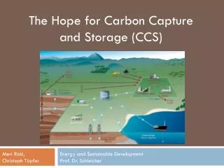
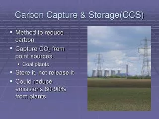
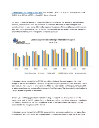
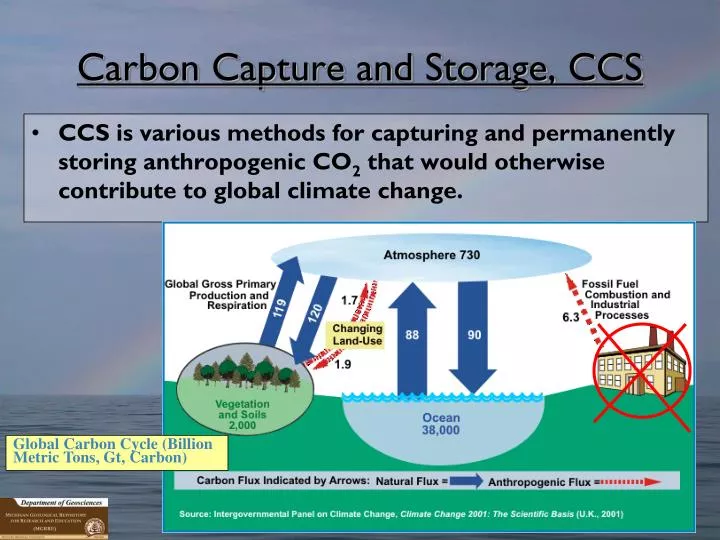
Carbon Capture and Storage, CCS. CCS is various methods for capturing and permanently storing anthropogenic CO 2 that would otherwise contribute to global climate change. Global Carbon Cycle (Billion Metric Tons, Gt, Carbon). Geological Sequestration ( GS).

E N D
Carbon Capture and Storage, CCS • CCS is various methods for capturing and permanently storing anthropogenic CO2 that would otherwise contribute to global climate change. Global Carbon Cycle (Billion Metric Tons, Gt, Carbon)
Geological Sequestration (GS) Geological media suitable for storage of CO2 in Michigan depleted oil reservoirs (+/- CO2/EOR) and deep, saline (brine-filled) reservoir formations ` ` CO2CRC
} MI Storage Potential ~40Gt MI Emissions ~93Mt/yr As much as 16,000ft of bedrock sedimentary strata (below glacial drift) Michigan’s Deep GS Injection Zones “Shallow” Carbonate and Sandstone Injection and Confinement Zones “Intermediate“ Carbonate Reef Injection and Confinement Zones “Deep” Sandstone Injection and Confinement Zones
Michigan Pilot Injection Test Project • MRCSP is one of seven U.S. DOE/NETL RCSP’s. • Eight-state region of IN, KY, MD, MI, NY, OH, PA, and WV. • Phase I Launched, fall 2003; Phase II commenced October 2005. • Michigan Basin site is one of three small scale CO2 injection test sites.
Results of Pilot CO2 Injection Test • Initial ~20 days of CO2 injection: >10,000 mt through 8.5 inch well casing • Variable injection rates to pipeline capacity: @600mt/day • Annualized injection rates: ~220,000 mt/yr (US CO2 emission rate is 6 Giga MT/yr ) 220,000/6e9 = 3 parts in 1 million • Data extrapolation suggest maximum injection rates: 440-660,000 mt/year (so what this doesn’t really scale well) Analysis and interpretations of injection data by: Joel Sminchak, Battelle Memorial
Hydrostatic Gradient:0.49 psi/ft Temperature:50°C Brine:300,000 ppm TDS Maximum Entrapped CO2 Saturation =0.2 Application:Large(???) Stationary Point Source (~80Mw)20 yr Active Injection; 280 year Recovery Model Parameters • Injection Rate =0.6 MMT/year for 20 yrs • Recovery Period =280 years • Target Formation Interval:1504-1799 m • Injection Interval:1707-1765 m • Well Diameter:8 5/8” casing Diana H Bacon Battelle Pacific Northwest
Non-technical Challenges to Implementation of Carbon Capture and Geological Storage for Greenhouse Gas Emissions Reduction Public understanding and acceptance Clear legal and regulatory framework to stimulate investor confidence Sufficient cost for GHG emissions (that exceed cost of CC&GS) through regulation Regional, National, and International Cap and Trade Programs/Carbon Tax