Download

1 / 16
160 likes | 304 Vues
Chapter 5 Ideal Filters, Sampling, and Reconstruction Sections 5.3-5.4 Wed. June 26, 2013. 5.3.1 Ideal Filters – Linear Phase. To avoid phase distortion:. for all ω in the passband , where t d is a fixed positive number. Then the response to a sinusoidal input is:.

E N D
Chapter 5Ideal Filters, Sampling, and ReconstructionSections 5.3-5.4Wed. June 26, 2013
5.3.1 Ideal Filters – Linear Phase • To avoid phase distortion: • for all ω in the passband, where td is a fixed positive number. Then the response to a sinusoidal input is:
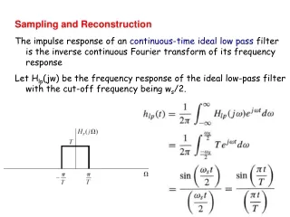
5.3.2 Linear Phase Low-Pass Filter • Let’s do this in the time domain: • and using time-shift property:
5.3.2 Linear Phase Low-Pass Filter Impulse response starts before t = 0 Non-Causal !
5.3.2 Linear Phase Low-Pass Filter • Ideal filters are non-causal, due to the unrealistic vertical cutoffs. • Design of realistic causal filters will be addressed later.
5.4 Sampling where T is the sampling interval, and n is the sample number.
5.4 Sampling where T is the sampling interval, and n is the sample number.
5.4 Sampling As shown in text equations 5.49 – 5.51, the Fourier transform of the sampled signal is:
5.4 Sampling Original signal: Sampled signal:
5.4.1 Reconstruction Original signal: Sampled signal: Apply ideal lowpass filter with bandwidth between B and ωs-B.
5.4.1 Reconstruction Sampling theorem: Original signal can be recovered perfectly as long as it is sampled above the Nyquist rate. The Nyquist rate is twice the bandwidth of the original signal: In practice, signals are oversampled, i.e.,
5.4.2 Reconstruction Interpolation (reconstruction) formula is derived from the impulse response of the ideal low-pass filter: This shows how to “connect the dots” between the samples to recover the original signal. Notice that every sample contributes to every time point. It is not as simple as connecting the dots with straight lines!
5.4.3 Aliasing If the sampling rate is below the Nyquist rate, aliasing occurs.