Download
1 / 50
500 likes | 659 Vues
PLANS FOR EXPERIMENT PROTECTION AT LHC. Introduction: Lessons from the past The L arge H adron C ollider LHC protection strategy Beam interlock system Failure scenarios Risks for the Expts LHC Experiment protection Beam conditions monitors, etc. Detectors damage threshold

E N D
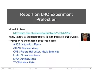
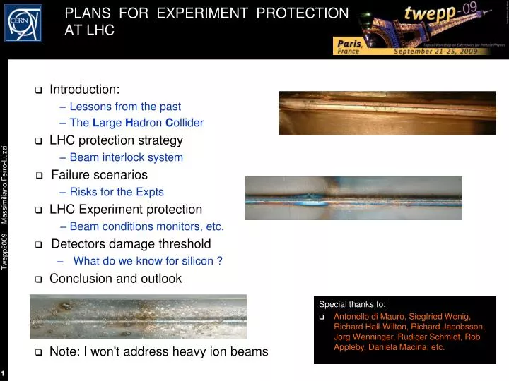
PLANS FOR EXPERIMENT PROTECTION AT LHC • Introduction: • Lessonsfrom the past • The Large Hadron Collider • LHC protection strategy • Beam interlock system • Failure scenarios • Risks for the Expts • LHC Experiment protection • Beam conditions monitors, etc. • Detectors damage threshold • What do we know for silicon ? • Conclusion and outlook • Note: I won't address heavy ion beams Special thanks to: • Antonello di Mauro, Siegfried Wenig,Richard Hall-Wilton, Richard Jacobsson, Jorg Wenninger, Rudiger Schmidt, Rob Appleby, Daniela Macina, etc.
It happens ... • SppS: • 198x: electrostatic separators adjusted for 315 GeV, instead of injection energy of 26 GeV => UA2 gets beam injected repeatedly into detector, no fast feedback from the Expt • LEP: • 1991: Quad polarity switched... consecutive splashes into L3, damage to BGO lumimonitor (later, in 1992, further failures with damage to endcap calorimeter...) • 1993: Quad failure ... Aleph loses fraction of VDET due to shorting of AC capacitor chips • RHIC: • 2000: Phobos: several missed aborts, lose 1-2% of their Si pad detector channels (other RHIC experiments affected as well). • HERA: • 2002: damage caused to H1 Si pad and strip detectors (BST) and their electronics. • Tevatron: • 2002: asynchronous dump, CDF loses six ladders of vertex detector due to chip failure Lessons: See J. Spalding in TeV4LHC April 2005 • it does happen! • better have a protection system in the experiment to trigger beam abort • better have some sort of monitor during injection (fast feed back to machine!)
Stored Energy of the LHC • A factor 2 in magnetic field • A factor 7 in beam energy • A factor 200 in stored energy! 360 MJ 2808x1.1 1011p 4x72x1.1 1011p LHC 2009-2010 target
Damage Potential of LHC Beams • LHC colleagues performed a controlled experiment with 450 GeV beam shot into a stack target to benchmark simulations. • Copper: • melting point reached at 2.4x10¹² p • clear damage at 4.8x10¹² p • Good agreement with simulation 1.2 2.4 7.2 4.8 x10¹² protons See V. Kain et al., Material damage test with 450 GeV LHC-type beam, Proc. of 2005 Part. Acc. Conf., Knoxville, Tennessee, and PhD Thesis by V. Kain, CERN-Thesis-2005-047 Definition for the LHC of a “safe” beam limit(setup beam, see later): 1012 protons at 450 GeV 1010 protons at 7 TeV (scaled from 450 GeV) about 3% of a full SPS batch Note: tests as described above do not correspond to the most typical impact of beam, there is a safety margin on the 450 GeV “safe beam” for typical accelerator equipment. But what about experiments/detectors ?
The LHC and the Experiments • CMS/Totem: • near dump • roman pots RF BEAM CLEANING • LHCb and Alice: • just near injection point • experimental dipole magnets + correctors • no TAS absorbers • LHCb VELO, similar to "roman pots" BEAM DUMP 8.5 km BEAM CLEANING • ATLAS/LHCf: • a cool place to be...
Typical Insertion Region ( Region Around Experiment ) • Here is CMS (same for ATLAS), symmetric at IP: • Here is LHCb (similar for ALICE): cryomagnet warm magnet absorber/ collimator TAS = absorber to protect triplet from IP primaries NB: Q1-3 contain also some corrector dipoles injection from SPS ! • No TAS • presence of dipole magnet + correctors MBXW...
LHC Machine Protection Beam modes: • Outside these two beam modes, movable detectors must be OUT • In this state, they should move OUT (but don't dump if not...)
LHC “Passive„ Machine Protection : Collimators / Absorbers • Almost entirely cryogenic ring • more than 20 km of superconducting magnets • Quench limits impose collimation! Lost protons must be intercepted with high efficiency before quench • instantaneous loss in a magnet (~10 m) required < 1010 p at 450 GeV, 106-7 at 7 TeV • Unlike HERA, TEVATRON, RHIC... the LHC cannot be operated without collimators (except at injection with low intensity). • At the LHC the collimators must define the aperture (primary + secondary) which has an important impact for Machine Protection:for most multi-turn failures the beam will hit collimators first ! • Monitoring: • BLM’s on collimators, on magnets • BPM’s, etc. • Try avoiding quenches by setting dump thresholds lower than quench values
LHC “Active„Machine Protection : Beam Interlocks • General strategy: • inject probe bunch (5x10⁹ p) • if OK (circulating), inject higher intensity batch • on dump trigger => extract beam in < 0.3 ms (1 turn 0.09 ms) • Abort gap: • continuously monitored, at least 3 us long • Beam Interlock System • Two redundant BeamPermit loops per beam around the ring • Beam Interlock Controller: • Makes AND ofseveralUserPermit signals • More than 3000 LHC user devices of the BICs (BLM's, BPM's, etc.) • If UserPermit signal is false, then BeamPermit is false => dump and block injection • BeamPresence • one flag per LHC ring • at least 5 uA in the ring (fast AC BCT) • ProbeBeam • True if SPS intensity < limit • limit = C x 1011 protons (C≤1) • if BeamPresence and ProbeBeam are false, then cannot inject into LHC • SetUpBeam • based on LHC current, energy dependent: • True if < 1012 (5x10¹⁰) protons at 0.45 (7) TeV. • If True, it allows masking some BIS inputs see LHC Design Report vol. 1 Main Ring
Impossible Failure Scenarios ... For the experiments, these are the worries: • Injection failures: • incomplete or unsynchronized kicker fire => mostly Alice & LHCb • wrong magnet settings in transfer line => mostly Alice & LHCb • wrong magnet settings in the LHC => everybody • Circulating beam failures: mostly caught by collimators • magnet failure / mishap => everybody • RF failure => everybody • collimator failure / mishap => everybody • Extraction failures: • underkick, unsynchronized beam dump => mostly CMS Expect Expts to be protected by "early" cryomagnet quench protection We'll see some specific examples later
What kind of particle rates ? • In terms of estimating particle rates to a detector, the only simple (though quite unlikely) LHC failure scenario is • Suppose a batch is injected with wrong magnet settings near an experiment (remember: a probe beam has < 1011 protons) • The batch is shot straight into the detector without traversing much material (little showering, less than x10 multiplication), beam size ~ 0.3 mm • Potentially, of order ~1013 p/cm2 (in <1ns) depending on the maximum value for the ProbeBeam and on the local shower multiplication • Very high flux density, but very local (could be quite catastrophic if readout chips happen to be on the trajectory) • Other possible failures (with grazing, showering,...) require detailed MC simulations • Work in progress • A few examples in the next slides
Example 1: TAS Absorber Grazing Case in ATLAS See Dariusz Bocian, LHC Project Note 335 ATLAS beam failures simulation: • Studied wrong settings of MCBX, D1 and D2: due to presence of TAS absorber, pilot beam can never hit directly the Inner Detector. • Thus, most dangerous case is when wrong magnet setting is such that beam scrapes first TAS and hits second TAS. • If a 5x10⁹ bunch is lost in ATLAS due to a single wrongly set magnet, the estimated radiation dose delivered to the b-layer is estimated to be < 5x10⁻³ Gy or ( Note: in terms of rate this is about 107 more than during a nominal bunch crossing, i.e. ~ 106 MIP/cm2) Injection energy D1 magnet (wrong) setting (should be about 6.4%) • Specially searched fortwo-magnet failures could deposit much more, but such failures are considered much less likely
Example 2: Extraction Failure and Effect on IP5 • Simulations for effect on CMS / IP5 due to unsynchronized abort and kicker prefire, see Drozhdin, Mokhov, Huhtinen, 1999 Particle Acc. Conference • kicker prefire: one kicker module fires alone; should not happen (system designed such that a firing module fires the other modules) • unsynchronized abort: quite likely to happen; kicker rise time ~3us => ~120 bunches swept BEAM DUMP • Results (for Pixel detector): • Integrated doses not so dangerous, • but rates are! • Up to 108 times higher instantaneous rates than during nominal running up to 108 x 106 MIP cm-2 s-1 !! BEAM CLEANING • These results led to addition of movable and fixed collimators at IP6 (TCDQ, TCDS) to intercept the bulk of the mis-kicked beam
Example 3: ALICE Beam Failures Simulation Studies Effect of kicker failures during injection • See B. Pastirčák et al., Radiation from Misinjected Beam to LHC, ALICE Internal Note 2001-03 Failure scenarios: • grazing: full batch (4.1x10¹³ p) missing the TDI beam stopper, worst case but very unlikely • sweep: prefire of kicker modules, ≈ 20 bunches escape TDI, expected several times/year (?) main contribution Results: • Accumulated dose during 10 years due to "expected" misinjections is (for Si Pixel Detector and electronics) about 1 krad (1% of total dose from primary collisions) • Energy deposition maps per accident in Alice detector (vertical section): "grazing" "sweep" Here, for Si, inner tracker: 100 rad ~ 109-10 MIP/cm2 cm cm cm cm rad rad
Example 4: Wrong Compensator Setting at Injection ( here beam2 IP8 ) • Beam2, 450 GeV • Wrong setting of MBXWH (horizontal compensator) • Beam can hit LHCb detector 1.0 to 0.55 of max B Nominal 0.06 LHC Project Report 1174 “LHCb Injected Beam Accidents” R.B. Appleby LHC Project Report 1175 “ALICE Injected Beam Accidents” R.B. Appleby
Example 5: wrong compensator or corrector settings at injection ( here beam1 IP8 ) Beam1 450 GeV Wrong MBXWH 1.0 to 0.35 of max B Nominal 0.06 • Injected beam does not need to come from nearby injection line! • Here beam 1 in LHCb (after almost one turn) • Valid for all experiments at LHC Beam1 450 GeV Wrong MCBXV 1.0 to 0.3 of max B Nominal 0.05 LHC Project Report 1174 “LHCb Injected Beam Accidents” R.B. Appleby LHC Project Report 1175 “ALICE Injected Beam Accidents” R.B. Appleby
Example 6: circulating beam D1 failure at 450 GeV ( here IP8 ) • Separation magnet D1 going down at 450 GeV • Beam mostly caught at primary collimators • Here, LHCb VELO would have an aperture of 5 mm radius around the beams LHC Project Report 1176 “LHC circulating beam accidents for near-beam detectors” R.B. Appleby
Example 7: Wrong Local Bump Take again IP8 / LHCb • Beams separated in Y (vertical) during filling, ramping, etc. • Typ. ~ 1 mm between beams at 7 TeV before colliding • Max. accessible separation at 7 TeV is a few mm • Bump can be local, transparent to rest of machine! • Example here at 7 TeV with two magnets • The lower the energy, the “easier” to make such a bump • At 450 GeV => accessible separation range amplified by factor 15.5, i.e. up to few mm x15.5 !! 7 TeV/beam Wrong (extreme) settings in 2 MCBX correctors acting coherently VELO aperture Normal case s/w interlocks will be in place
BCM +others Magnet Roman pots LHC Experiment Interlocks Beam_permit: • In each experiment, several systems (typically 3 or 4) in “and” mode must be alive and deliver a User_permit • If one system remove the User_permit, it triggers a beam dump • Both beams are dumped • Recovery procedure after post-mortem data analysis (emergency buttons are also implemented in some experiments…) Injection_permit: • Separate interlock based on same transmission hardware (signals to SPS extraction) • Allows inhibiting injection into LHC, e.g. when • Detector not ready for injection • Bad injection detected during a fill, requires stopping injection without dumping the stored beam
Typical LHC Experiment Protection System about 2 m • One set of diamond sensors on each side of IP: • Stand-alone system using a few polycrystalline CVD diamond pads • UPS powered, with few minutes autonomy • Post-Mortem analysis capability • FPGA-based dump logic: • input: measured rates • output: UserPermit signal • Unmaskable input to local BIC • On trigger, dump both beams • Expected ready from "day 1" • Must have high availability, reliability, efficiency • BCM (beam conditions monitor) must protect detectors against circulating beam failures a few cm IP CVD, 1 cm2 0.3-0.5 mm thick 1 MIP ~ 1 fC
ATLAS (1) towards IP SIDE A BLM • Beam Loss Monitors (BLMXD.01L1/R1.CH0N_ATLAS) • 2 x 6 pCVD diamond detectors (8 x 8 mm2) • z = ± 345 cm and r = 65 mm • 40 ms integration time, pA to mA • Readout chain of LHC BLM system with modified BLMTC FPGA firmware • Abort signal at front panel • Receive PM signal • Beam abort condition • 2 in a group of 3 detectors above threshold SIDE C At nominal 1e34 cm-2 s-1 Noise Collisions Thres. Damage ~10 pA ~15 nA 50 nA (?) > 1 uA?? towards IP
ATLAS (2) • Beam Conditions Monitors (BCM) • 2 x 4 pCVD diamond detectors (8 x 8 mm2) • z = ± 184 cm and r = 55 mm • Fast readout time • Single MIP sensitivity with sub-ns time resolution Time of flight measurement distinguish collisions – background (ΔT(A/C) = 2d/c) • Beam abort condition (not used at start-up) • 3 sensors above high threshold ( 5 MIPS) AND • 4 sensors above low threshold (0.5 MIPS) C A BCM Beam Pipe Pixel Detector See M. Mikuz et al., NIMA 579 (2007) 788-794 d d/c = 184 cm/c = 12.2 ns = ~ 25ns / 2 Monitor beam halo by out of time signals vs collisions
CMS (1) see L. Fernandez-Hernando et al., NIMA 552 (2005) 183-188 • BCM1L • Leakage current monitor • Polycrystalline Diamond • Usage: Experiment protection • BCM1F • Bunch by bunch monitor • Single crystal Diamond • Usage: Pixel protection • BCM2 • Leakage current monitor • Polycrystalline Diamond • Location: z=± 14.4m, r=29cm, 4.5cm • 8 stations in ϕ, 24 sensors total
CMS (2) • Initially only 8 diamonds (4 per end) in inner ring on BCM2 will be “active” in asserting BEAM_PERMIT • BCM1L hardware will be connected to the ABORT from the beginning, however thresholds will NOT be set until after a suitable commissioning period with beam • BCM1L detectors and inner ring of BCM2 are at ca. 4.5cm radius, approximately the same as innermost layer of pixel detector • Initial threshold for BCM2: RS1 ~ 10 uA (40 us) • Thresholds are per diamond. No coincidence required. • Has been running stably for > 6 months, w/o spurious triggers At nominal 1e34 cm-2 s-1 Noise Collisions Thres. Damage <10 pA ~15 nA 10 uA > 18 uA
ALICE (1) BCM A2 z = +13.5 m 4 diamond sensors BCM A1 z = +4.5 m 4 diamond sensors BCM C z = -19 m 8 diamond sensors L BLMs R VO-A scintillators VO-C scintillators RADMON
ALICE (2) • The UserPermit is based on BCM-CFC-TELL1 chain as in LHCb. • Fast abort on RS2 (2x40ms CFC integration frames) coincidences: Dump beam if 3 of 4 adjacent diamond sensors show current > thrRS2 • Slow abort on SRS32 (32x40ms): Sorting out the two highest and the lowest of 8 sensors, dump beam if SRS32 > thrSRS32 • Current estimate for dump thresholds (to be x-checked …): • thrRS2 ~ 5000 nA , thrSRS32 ~ 250 nA Noise Collisions Thres. Damage <100 pA ~100 pA ~ 5 uA ~ mA BCM currents from FLUKA simulation of injection failures by B. Pastirčák (ALICE Int. Note 2001-03), updated in Nov 07 TDI sweep(pilotbunch 5 × 10⁹ p) Injection test Aug 9-11 2008 Beam through ALICE I [nA] TDI grazing (pilot bunch 5 × 10⁹ p) time
LHCb (1) VELO • Each BCM station composed of 4 or 8 CVD diamonds • Mounted on the beam pipe, about 6 cm away from beam axis • Asymmetric layout of BCM around IP (space availability) • Diamonds readout: integrated rates in 40 us (later upgrade to 25 ns ?) • Use stand-alone readout board for algorithm on dump trigger decision • Simulations ongoing (relate VELO rates to BCM rates in failure scenarios) BCM beam pipe support diamonds Noise Collisions Thres. Damage <10 pA ~1 nA few uA > ?? uA
+/-5 mm Beam 30 mm 30 mm LHCb's Special: Vertex Locator • Injection: no material at r<27 mm Velo open (OUT) • During stable beam Velo closed (IN) • Final position adjustable in y and in x to center beam in the hole (axial geometry for RZ trigger !) • It must be possible to adjust "beyond" nominal beam axis (beam position not guaranteed...) • Microswitches to detect Velo is OUT (both halves) • Microswitches and hard stops to prevent crashes 5 mm radius 0.25 mm Al foil 21 r-phi Si modules per side 0.25 um CMOS ASICs (Beetle)
BCM Magnet VELO pos LHCb VELO Protection System "OUT" 30 mm "IN" 5 mm • Microswitches in X on each half to check that VELO is in garage position (OUT) • Read out by PLC which generates Device_out signal • LHC flag Device_allowed transmitted via reliable network to the Expts. If False, movable devices must be in OUT position • If both LHC flag Device_allowed and VELO flag Device_out are false, then LHCb UserPermit is false => dump the beam, prevent injection • VELO motion is "slow", of order 0.1 mm/s • Can move over nominal beam axis and/or beam can move to the detector! fast protection needed ! BCM must detect increase in rate (over normal minimum bias events) due to a possible beam-velo foil scraping, must work for both beams beam AND Device_out = true Device_out = false actual beam nominal beam axis
Damage thresholds for detectors What are the most exposed / most sensitive detectors ? What are their damage thresholds ? Why do we care ? • Detectors are designed, built and installed: but operation procedures can be changed • HV and LV on/off at injection or with “non-physics” circulating beam ? • Feedback to the machine • Definition of intensity limit at injection • Currently H/W 1011 protons and S/W 1010 • Improvements on future detectors (at even higher beam intensities...)
Ubias Risks for LHC Vertex Detectors • For comparison: • Atlas/CMS pixel (r=4.3cm): order of 0.02 MIP/cm2 per pp interaction • LHCb VELO: order of 0.5 MIP/cm2 per pp interaction • MIPs through pixel detectors due to pp collisions in IP1/5 in a nominal year ~ 1017...18 • One nominal LHC bunch: 1011 p • Full nominal LHC beam: 3 x 10¹⁴ p Problems with beam losses for the silicon: • Heat deposit: not a problem ? (for the likely failures) • Thermomechanicql effects ? Seeds for crqcks ? • Extra radiation damage, eating up the "budget" • not so critical: LHC Si detectors designed to sustain "huge" doses (few 1014neq/cm2 ~ 10 Mrad) ; • but watch out anyway! • Sudden high rate can induce large voltage in the Si detector • becomes essentially conductor => bias voltage boundary moves to another place... zap or no zap ? • e.g. SiO2 breaks at ~ 1V/nm • direct hit to FE chip can be even worse (lose full chip, i.e. many channels... see CDF accidents) The keep-it-always-on-or-not dilemma: • Keep detector always ON for stability ? • no charge up effects, no temperature effects, etc. • Reduce risk during injection by turning OFF HV ? (or even LV off)? • unstable at turn-ON Si Ubias insulator What do we know about LHC Expt Si detector and resistance to high rates ?
High Particle Rate Tests On LHC Silicon Detectors ATLAS and CMS tests at CERN PS beam: • 24 GeV, 1 or few-bunch batch (bunch: 42 ns long, ~1011 p, separation 256 ns), with peak bunch density of ~ 3x10¹⁰ p/cm2. • Detectors biased and FE electronics ON • ATLAS: • See A. Andreazza, K. Einsweiler, C. Gemme,, L. Rossi, P. Sicho, NIM A 565 (2006) 50–54, Effect of accidental beam losses on the ATLAS pixel detector • CMS: • See M. Fahrer, G. Dirkes, F. Hartmann, S. Heier, A. Macpherson, Th. Müller, Th. Weiler, NIM A518 (2004) 328–330, Beam-loss-induced electrical stress test on CMS Silicon Strip Modules Laser tests (not exhaustive): • Atlas silicon strip: 1064 nm LASER (1 W) • K. Hara,T. Kuwano, G. Moorhead, Y. Ikegami, T. Kohriki, S. Terada, Y. Unno, NIM A 541 (2005) 15–20, Beam splash effects on ATLAS silicon microstrip detectors evaluated using 1-w Nd:YAG laser • Atlas silicon strip sensors: LASER (2 types) • T. Dubbs, M. Harms, H. E-W. Sadrozinski, A. Seiden, M. Wilson, IEEE Trans. Nucl. Sci. NS47 (2000) 1902, Voltages on Silicon Microstrip Detectors in High Radiation Fields
ATLAS High Particle Rate Test • Andreazza et al., NIM A 565 (2006) 50–54 «The results of the PS experiment therefore indicate that the loss of a LHC ‘‘pilot beam’’ of 5x10⁹ protons should not make any sizeable permanent damage to the performance of the ATLAS pixel detector. This accident will, very likely, require a reloading of the configuration parameters in a large fraction of the pixel detector. »
CMS High Particle Rates Test • M. Fahrer et al., NIM A518 (2004) 328–330 «There is strong evidence that CMS silicon strip modules will survive a beam loss, because the fast breakdown of bias voltage protects electronics and sensors, especially the dielectric layer and the polysilicon resistors.»
A Recent LHCb VELO High Rate Test VELO/LHCb "High Rate Test„ It‘s here Resto2 Main bldg
A Small Scale Experiment Module mounted close to the PS booster (PSB) beam dump • Proton beam of 1.4 GeV kinetic energy • Intensity from 2e9 to 9e12 p/bunch • 1 to 4 bunches (4 rings), we use a single bunch (ring 3) • Beam spot size rms ~ 2-4 mm , bunch duration rms ~ 20-60 ns Velo module
The Victim: “Module 48” • LHCb/Velo spare from production • Back-to-back R & Phi sensors • 2048 AC coupled n-on-n strips / side • 16 FE chips (IBM 0.25 µm) per side, all configured but only 8 per side read out • Mounted in the beam line • Cooled to +1 ˚C (LV on) with vortex tube (8 bar compressed air) • Fluorescent screen to view the beam • Insert/retract from beam line • Remote control and read-out • Heavy radiation environment ! • Backsplash at every beam dump • ~ 1 kGy in a few months
FE inputs (2048 channels) Vfp LV (VDD) VDD bonds (16x4) protection diodes CFB CLV CG bond wires pre-amp GND bonds (16x5) LV (GND) GND probe Al RC filter Rbias 10 pF SiO2 CAC 10 MΩ HV return (GND) n n+ Osc. GND QRC QRC 10 pF RDET CDET CRC CRC 10 MΩ 22 nF RRC HV probe RRC 1 kΩ HV bias (-300V) p+ Electrical model – static case CDET = 1 nF/2048 ch. RDET = 1-100 MΩ/2048 ch. CAC = 250 nF/2048 ch. Rbias = 1 kΩ x 2048 ch. CRC = 10 nF RRC = 5 kΩ CFB = 400 fF (per ch.) CG = 10 pF (per ch.) CLV = 32 x 100nF
The measurement sequence - observables • Intensity steps: 2x10⁹, 2x10¹⁰, 2x10¹¹, 2x10¹² & 9x10¹² • Each step: LV/HV off, LV on/HV off, LV on/HV 150 V & LV on/HV 300V • Each beam ‘shot’ follows the same pattern • A set of standard measurements • I/V of both sensors • Noise & pedestal data • Test pulse data at +1.5, 0 and -150 V • Insert the module, acquire during the shot • 14 consecutive triggers of front-end data • Voltage on hybrid GND and sensor bias via oscilloscope • Beam spot image via a a camera • Repeat the same set of measurements • Shots on two sensor positions • Shots on five front-end chips (here only LV on/off matters) B15 B14 B13 B12 B11 B10 B9 B8 Phi
Beam images Beam line camera on fluorescent screen Combined R-Φ sensor front-end data
I/V curves • I/V curves in-situ between each shot • Superimpose temperature corrected I/V curves • Small increase probably due to accumulated dose • Rough estimate between first and last curve: ~3.5x10¹² 1-MeV-neq /cm2 (~1 kGy) • Work in progress • Correlate with radiation monitoring data Leakage current increase ~ compatible with ~3.5e12 1MeVn_eq/cm2 seen by whole detector due to many bcksplashes from the dump
Thermal image: No hot-spots The majority of the shots hit this area
Noise & Pedestals • Noise & pedestals measured in-situ between each shot • Plots show date taken towards the end of the program • No change visible • Detailed analysis is in progress
Test pulse response – post-zap • Test pulse response • ‘booster’: in-situ after a couple shots (module almost fresh) • ‘lab’: lab measurement after the full program • Gain difference due to different analogue drivers/receivers • Bad channels identical to production QA • No significant effect observed due to beam shots
time [µs] Voltage across the sensor vs. time • Oscilloscope measurements • Hybrid GND • Backplane • 1 sample / ns • Ground reference arbitrary • Huge ground bounce • Large pick-up • Plot Vbackplane-VhybridGND • Two distinct features • Sharp rising edge (50 ns) • Slow charge-up
time [µs] The first 50 ns … 6 GV/s 2.5 GV/s 2 GV/s
Shots on the FE chips • 56 shots on the FE chips: 2x10⁹ – 2x10¹¹ p/bunch • No destructive latch-up • Design rules include structures to prevent latch-up • Seems to be effective! • SEU analysis in progress: none observed so far • Requires large energy deposited in small volume • Nuclear reactions necessary • Cross-section very low • Triple-redundant registers: corrected every 2 ns
Summary of LHCb High Rate Test • The PS booster provided beam to emulate specific LHC beam injection failures • 200 ns shots (+/-2rms), 2x10⁹ to 9x10¹² protons in ~1cm2 • A VELO strip module was subject to a large number of shots • Two positions on the sensor, five FE chips • Different conditions on LV and HV • Survived 9x10¹²p on sensor with 0, 150, 300 V bias, LV on or off • Survived 2x10¹¹p on the FE chip (LV on or off) • No visible change in performance • I/V curves, noise, pedestals, thermal imaging, … • Saving graces ? • The whole sensor responds as a unit • Large area sensor – many channels • CAC >> CRC (+CDET) • Protection diodes on the FE inputs • Triple-redundant registers in FE chips • Analysis & measurement still in progress
Summary and Outlook • LHC is very different from what has been seen so far: • new (total beam) energy domain • cannot run without collimation (cryo/quenches) • Machine protection will play a key role (especially at turn-on) • passive (collimators) , active (beam interlocks, dump/inject) • Expts have developed own (to some extent, common) protection system • Beam Conditions Monitor (CVD diamonds) + other detectors => dump trigger • Should take care of circulating beam failures (redundant with machine protection) • Must have high availability, reliability, efficiency • Feed-back to stop injection is implemented • Close collaboration with machine colleagues • Not all possible failure scenarios for all IP's have been simulated or studied • Not all exposed detectors have been stress-tested with high particle rates... • Showed some recent results on LHCb/VELO damage threshold • Full chain tests ongoing (some already done) • Thresholds to be set and fine tuned with beam Work in progress
vivum HV bias reduced to 0 V Post-mortem – why did it survive? • Deposited energy (in 300 µm Si) • 9x1012 x 24000 x 3.6 eV => 0.12 Joule in ~200 ns • Temperature increase in 1 cm2 x 0.3mm Si < ~ 2 ˚C • Maximum SPS injection train (288x1011): 0.4 Joule / 10 µs • Local energy store: the RC filter • 10 nF @ 300V => 0.5 mJ • Absorption volume critical • Massive ionisation in biased silicon • QRC(300V) = 3 µC • Deposited charge @ 2x10⁹: 7.5 µC • Possible transient damage • Current through front-end • AC coupling diode • Voltage on front-end input • Fast HV ramp-down