Download
1 / 14
150 likes | 357 Vues
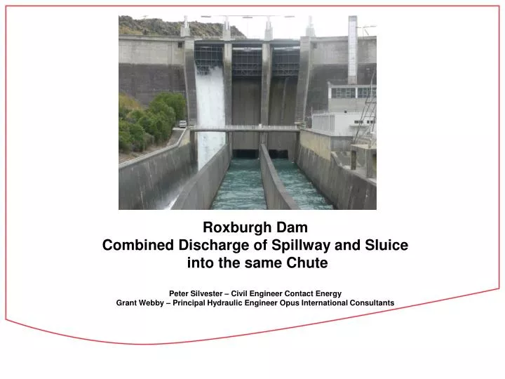
Roxburgh Dam Combined Discharge of Spillway and Sluice into the same Chute Peter Silvester – Civil Engineer Contact Energy Grant Webby – Principal Hydraulic Engineer Opus International Consultants. Roxburgh Dam - Location. Roxburgh Dam. Roxburgh Dam. Commissioned 1956

E N D
Roxburgh DamCombined Discharge of Spillway and Sluice into the same ChutePeter Silvester – Civil Engineer Contact EnergyGrant Webby – Principal Hydraulic Engineer Opus International Consultants
Roxburgh Dam - Location Roxburgh Dam
Roxburgh Dam Commissioned 1956 50m high concrete gravity 320 MW power station Mean flow 507 cumecs PMF 7,000 cumecs
Roxburgh Dam Spillway Three Spillway Gates 15.2m wide x 13.4m high. Discharge capacity 4,750 cumecs Two diversion sluices 7.1m wide x 8.7m high. Discharge capacity 2,900 cumecs. Combined total discharge capacity 7,650 cumecs.
Roxburgh Dam Spillway Spillway chute 3 dewatered
Sluices 7.1m wide 8.7m high • Diversion Sluices
Physical Hydraulic ModelUniversity of Auckland • Tests covered: • Sluice only operation - 25 • Spillway only operation - 25 • Combined operation - 125 • Total tests 175
Physical Hydraulic Model Results • Maximum pressures along sluice
Physical Hydraulic Model Rooster Tails Sluice only operation
Gate Tests Jan 2013 Sluice 2 opened 6.77m (78%). Discharge 862 cumecs.
Conclusions • Physical hydraulic model investigations supported by prototype testing have successfully proved for the Roxburgh Dam case that simultaneous discharge from a spillway gate and a low level sluice gate into the same chute is feasible and will produce smooth merged flow lines. • For sluice only operation the discharge will not pressurise the sluice tunnel. • Spillway only operation will pressurise the sluice tunnel only at high lake levels and gate openings greater than 40%. • Combined spillway and sluice operation will pressurise the sluice tunnel only at high lake levels and spillway gate openings greater than 40%. • The water levels induced in the sluice gate chamber by the back pressure from spillway only or combined spillway and sluice operation are unlikely to flood the middle gallery in the dam where the sluice gate controls are located. However further prototype tests are desirable to confirm the extreme water level values observed in the model tests. • Although the sluice is back pressured by the spillway the discharge from the sluice is not reduced. • ‘Rooster tail’ behaviour along each side wall at the sluice exit into the spillway chute could threaten the access bridge to the power station under high sluice only flow conditions at a high lake level. • Roxburgh Dam can safely pass the PMF inflow using the combined discharge from both the spillway and sluice gates fully open at a lake level of RL 132.3m (I.e. with 1.2m freeboard).