Download
1 / 25
280 likes | 627 Vues
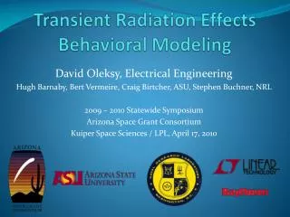
Introduction to radiation effects and modeling of radiation damage. Rubén García Alía , on behalf of the R2E project. Approach & Requirements. PHYSICS MODELS. RADIATION ENVIRONMENT. ELECTRONIC COMPONENTS. RADIATION EFFECTS ANALYSIS RADIATION TESTS MITIGATION.

E N D
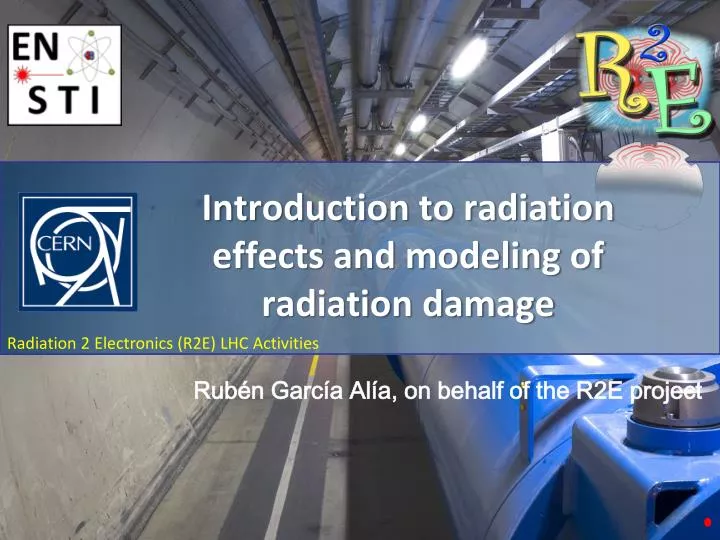
Introduction to radiation effects and modeling of radiation damage Rubén García Alía, on behalf of the R2E project
Approach & Requirements • PHYSICSMODELS • RADIATIONENVIRONMENT • ELECTRONICCOMPONENTS • RADIATION EFFECTS ANALYSISRADIATION TESTSMITIGATION
Why do we (at CERN) care about radiation effects? • Commercial components used in systems operating in or near the LHC-tunnel (power converters, cryogenics, QPS system…) • Intense radiation fields at the locations of operation • SEEs, TID and DD in components and systems affect the operation of the accelerator (beam dump, etc.) • Need to test,monitor, mitigate and predict (R2E project).
Accelerators: Radiation Sources • Direct beam Losses • Collimators and collimator like objectsinjection, extraction, dump • levels usually scale with beam intensity & energy • Beam/Beam, Beam/Target Collisions • around experimental areas • scale with luminosity/p.o.t. & energy • Beam-Residual-Gas • circular machines: all areas along the ring • scales with intensity, residual gas density & energy • Synchrotron radiation(lepton machines) • RF (e.g, during conditioning) • Radiation sources(irradiators, calibration, tomography, etc.)
Radiation effects on electronics • Total Ionizing Dose Effects (TID) and Displacement Damage (DD): • Cumulative effects, easier to predict • LHC absolute values typically not critical (especially in shielded areas) • Scaling of components positive for TID (smaller oxides) • Single Event Effects (SEEs): • Stochastic events, which can happen “any time” and are therefore harder to predict • Absolute levels are high, even in shielded areas (neutrons still make it through!) • Most effects are constant with scaling (smaller volumes compensate lower critical charges) but they can also increase (proton direct ionization, etc.)
Effects and CERN Radiation Levels ISS Sea Level Space & Deep Space Avionic R2ESingle-Event Effects MaterialDamage R2E Cumulative Damage LHC + Experiments COTS Systems Hardened Electronics Electronics Damage CustomBoards with COTS
FLUKA environment simulation input • FLUKA simulations of the LHC radiation environment • Detailed geometry and radiation source description • Scoring of integral (total dose, 1 MeV equivalent neutron flux, high energy hadrons, thermal neutrons) and differential (particle energy spectra) quantities
FLUKA environment simulation output • Radiation levels as a function of location • Strongly depend on the position (shielding, angle with respect to interaction point, etc.) • Particle energy spectra • For SEEs, the hadron species and energy distribution can be highly relevant
Particle Energy Spectra hardness LS = Lightly Shielded (RR) HS = Heavily Shielded (UJ)
SEE categorization • Soft (non-destructive) errors • Single Event Upset (SEU): bit flip induced in a digital element due to an ionizing particle. No permanent damage is induced as the bit can be rewritten (SRAM memories, logic devices) • Single Event Transient (SET): momentary voltage excursion at a node in semiconductors which can propagate to the output of the component (linear circuits, opto-couplers) • Hard (destructive) failures • Single Event Latchup (SEL): potentially destructive triggering of parasitic pnpnthyristor structure with a resulting current increase, which if the power supply is maintained, can destroy the device through thermal effect (CMOS structure) • Single Event Gate Rupture (SEGR): formation of a conducting path in the gate oxide due to a high field generated by high current (power MOSFETs) • Single Event Burnout (SEB): destructive triggering of a vertical n-channel transistor accompanied by regenerative feedback (power MOSFET biased in the OFF state, blocking a high drain-source current) Source: ECSS handbook – Calculation of radiation and its effects and margin policy handbook (list not complete)
Energy deposition mechanisms • Direct ionization: • “Continuous” energy loss from the environmental particle directly causes the SEE • important to correctly model the environment, but energy deposition relatively simple (through LET and Sensitive Volume dimensions) Fe26+ Edep~LET*d • Indirect ionization: • Discrete nuclear interaction (spallation, fragmentation, fission) between environment particle and device nucleus generates secondary ionizing particles • Accurate modeling requires detailed information of environment, device materials near the SV and nuclear interactions He4+ n Mg12+
Electronics: Energy Areas of Interest Thermal neutrons: n+10B→7Li+4He Intermediate energy neutrons: low energy elastic/inelastic products Inelastic interactions: n+28Si→25Mg+α → 28Al+p → 27Al+d →24Mg+n+α →26Mg+3He +p/n/p/etc.->Cu/W/Hf,… Low energy charged hadrons: direct ionization (relevant for very sensitive technologies)
SEE Rate Prediction • Environment: • typically particle LET or energy spectra • from measurements, simulations, models, etc. • atmospheric-like, outer space, Earth radiation belts, high energy accelerators… • Device response: • typically an error cross section as a function of particle LET or energy • from SEE measurements, models, simulations, etc. • Can be very different even for “electronically identical” devices • SEE ratefor a given device in a certain environment
Radiation field and device sensitivity + + Reality
Practical (simplified) example: FGClite project • 1000 units, 75% in LHC tunnel (Ф~5·1011 HEH/cm2/yr), 25% in RR and UJ (Ф~3·109HEH/cm2/yr) • Critical components: ADC (3 per unit, potentially SEL sensitive) and FPGA (4 per unit, potentially SEL and/or TID sensitive) • Both SEL cases lead to the loss in the current measurements for the magnets and will therefore result in a beamdump • Radiation hardness requirement: one dump per year • Total fluence per component type: 1015 HEH/cm2/yrfor ADC and FPGA • Combined cross section needs to be below 10-15 cm2 to satisfy the requirement, therefore the test fluences (and dose) required is extremely large
Low error count statistics • For N>50, sigma is equal to the square root of N. Therefore, if we consider a 95% Confidence Level, one can take N±2N1/2 • For N equal or less than 50, use 95% confidence tables. For example, to have a 95% confidence level that a component will not fail before a fluence of 1015 HEH/cm2, a fluence of 3.7·1015 HEH/cm2 needs to be reached without failure • In order to reach such levels, a significant quantity of components needs to be tested in parallel • Plus uncertainty sources such as: part to part and lot to lot variability, difference between test and operational environment, etc. • Heavy ion testing can be a “short cut” as it can guarantee very low proton cross sections “The Concept of Confidence or Fiducial Limits Applied to the Poisson Frequency Distribution” by W. E. Ricker, Journal of the American Statistical Association, v 32, (1937) pp. 349-386
SEL: Energy Dependence x 10 1 GeV 10 GeV Schwank et. al. 2005 (IEEE TNS)
Conclusions • Importance of estimating the operational failure rate for a component and its impact on the system • Challenges in the LHC context: complex (and evermore intense) mixed radiation field and commercial (and evermore sophisticated and sensitive) electronics • Testing is essential • Selecting the test environment and target fluences (application driven) • Characterizing the device’s response • Extracting a meaningful operational failure rate from test results (modelling, assumptions, etc.)
Further reading on SEEs • M. Brugger, “Radiation damage to electronics at the LHC-a first analysis” TWEEP 2011 • M. Brugger, “Introduction to FLUKA radiation to electronics” RadSol Meeting 2011 • K. Roedet al., “Methods for measuring mixed field radiation levels relevant for SEEs at the LHC” IEEE TNS vol. 59, NO. 4, Aug 2012 • R. Baumann, “Neutron and alpha particle effects in electronics” RADECS 2012 Short Courses • J. R. Schwanket al., “Effects of particle energy on proton-induced single-event latchup” IEEE TNS, vol. 52, NO. 6, Dec 2005 • E. Petersen, “Single Event Effects in aerospace” IEEE Press • B. Sierawski et al., “Impact of low-energy proton induced upsets on test methods and rate prediction” IEEE TNS, vol. 56, NO. 6, Dec 2009 • R. Harboe-Sorensen et al., “From the reference SEU Monitor to the technology demonstration module on-board PROBA-II” IEEE TNS, vol. 55 NO. 6, Dec 2008 • R. Garcia Alia et al., “SEU measurements and simulations in a mixed field environment” RADECS 2012 proceedings, accepted for IEEE TNS • H. H. K. Tang, “Nuclear physics of cosmic ray interaction with semiconductor materials: particle-induced soft errors from a physicist’s perspective”
“LHC”-life example: SEL on CPLD • A Complex Programmable Logic Controller (CPLD) was tested using 60 MeV protons • No SEEs were observed for the three devices tested before these started failing due to total ionizing dose effects (cumulative) after 120 Gy. • The component was then exposed to high energy particle radiation at an LHC-environment. Permanent destruction of the part occurred in the early stage of the test. • Importance of testing in the actual operation environment (not always feasible in a systematic way) and of being able to model/predict the error rate (energy dependence knowledge, for example)
SEL & Fission: Energy Dependence • High-Z materials (namely tungsten) are often used in the interconnection layers of the memories, near the sensitive volumes • Energetic hadrons can induce fission in these materials, producing very high-LET fragments that can dominate the SEE cross section (p,f) cross section in W 134 mb Factor ~35 between max. test energy and saturation (CPLD example!) 3.7 mb 230 MeV 3.4 GeV
SEL: Energy Dependence • Important possible dependency for high-energies • Strong impact on various radiation environments Compared to 100 MeV No W W fromrev. Eng. Full layerof W