Download
1 / 33
561 likes | 1.38k Vues
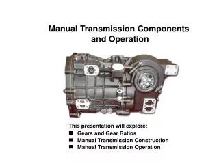
6. Manual Transmissions Parts and Operation. Figure 6–1 A five-speed transmission gear train. Power enters through the input shaft and leaves through the transmission output shaft. Figure 6–2 Bearings support the input shaft, countershaft, main shaft, and speed gears.

E N D
6 Manual Transmissions Parts and Operation
Figure 6–1 A five-speed transmission gear train. Power enters through the input shaft and leaves through the transmission output shaft.
Figure 6–2 Bearings support the input shaft, countershaft, main shaft, and speed gears.
Figure 6–3 The torque capacity of a transmission is determined by the size of the gear and bearings used. The greater the distance, usually measured in millimeters such as 77 mm, between the main shaft and the countershaft, the greater the torque capacity.
Figure 6–4 (a) The input shaft rotates in a clockwise direction; the countershaft rotates in a counter clockwise direction and the first–reverse gear drives the output shaft in a clockwise direction. (b) When meshed with the idler gear, the first–reverse gear will be driven in a counter clockwise direction. A simple (single) idler is shown.
Figure 6–5 A typical shift mechanism showing the shift detents designed to not only give the driver a solid feel when shifting but also to prevent two gears from being selected at the same time. The shifter also prevents shifting into reverse except from the neutral position.
Figure 6–6 The shifter fork fits into the groove of the synchronizer sleeve. When a shift is made, the sleeve is moved toward the speed gear. The sleeve presses the stop ring (synchronizer ring) against the cone area of the speed gear. The friction between the stop ring and the speed gear causes the speed of the two to become equal, permitting the sleeve to engage the gear clutch teeth of the speed gear. When this engagement occurs, the shift is complete.
Figure 6–8 Synchronizer keys are attached to the clutch hub and push against the synchronizer ring when the sleeve is being moved during a shift. Notice the grooves on the synchronizer ring. These grooves prevent lubricating oil from becoming trapped between the ring and the cone surface of the speed gear. The grooves also help the ring release from the cone surface when a shift is made out of a gear.
Figure 6–9 A shift sequence starts when the shift fork is moved by the driver. (a) Applying a force on the sleeve that moves it toward the speed gear. (b) The sleeve and the inserts contact the stop ring (blocking ring). (c) The synchronizer ring (stop ring) engages the cone on the speed gear, causing both assemblies to reach the same speed. (d) The shift is completed when the internal teeth of the sleeve mesh with the gear clutch teeth of the speed gear.
Figure 6–10 The shape of the splines helps prevent the transmission/transaxle from jumping out of gear during acceleration and deceleration.
Figure 6–11 Exploded view of a triple-cone synchronizer. The inner and outer rings rotate with the synchronizer sleeve while the middle ring rotates with the speed gear.
Figure 6–12 In neutral, the input shaft and the countershaft are rotating if the clutch is engaged (clutch pedal up), but no torque is being transmitted through the transmission.
Figure 6–13 In first gear, the 1–2 synchronizer sleeve is moved rearward, locking the first speed gear to the output shaft. Torque is transmitted from the input shaft to the countershaft and then to the output shaft.
Figure 6–14 In second gear, the 1–2 synchronizer sleeve is moved forward, which locks the second speed gear to the output shaft.
Figure 6–15 To achieve third gear, the shaft linkage first centers the 1–2 synchronizer sleeve and then moves the 3–4 synchronizer sleeve rearward, locking third speed gear to the output shaft.
Figure 6–16 In fourth gear, the 3–4 synchronizer sleeve is moved forward, which locks the fourth speed gear to the output shaft.
Figure 6–17 To achieve fifth gear, the shift linkage first centers the 3–4 synchronizer sleeve and then moves the fifth synchronizer sleeve toward the fifth speed gear, locking it to the output shaft.
Figure 6–18 Torque flows through the transmission in reverse gear. Note that the idler gear drives the 1–2 synchronizer sleeve gear, which is splined to the output shaft.
Figure 6–19 Cutaway of a T56 six-speed transmission showing all of its internal parts.
Figure 6–20 When the gearshift lever is moved, the internal linkage (shift rails) moves the shift fork and synchronizer sleeve to shift gear speeds.
Figure 6–21 The internal shift mechanism includes the shift detents and the interlock to keep the shifter from selecting two gear ratios at the same time.
Figure 6–22 Getting into reverse requires extra effort to overcome a strong centering spring.
Frequently Asked QuestionWhat Is a Remote Shifter?Some rear-wheel-drive manual transmissions such as the Getrag MT-82 used in newer Ford Mustangs use a remote-type shifter. ● SEE FIGURE 6–23. The use of a remote shifter allows the shifter to be placed in the same location as other types of manual transmissions such as the Tremec TR-6060 (lower unit) used in the Shelby Mustang. Using a remote shifter allows the engineers to isolate road noise for a quieter cabin but at the expense of the direct feel that an internal shifter can provide.
Figure 6–23 A remote shifter (upper unit) is used to locate the shifter inside the vehicle in the same location of another type used in a similar vehicle.
Figure 6–24 Notice the gear teeth in this transmission that those on the fifth gears have a finer pitch and a greater helix angle, to produce quieter operation while cruising.
Figure 6–25 Two gears, (3) and (4), are press fit onto the cluster gear in a TR-3550 transmission.
Figure 6–26 A Borg-Warner T5 five-speed transmission shown with the shifter cover removed.
Figure 6–27 The types of frictionless bearings are ball bearings (a), straight roller bearings (b), needle bearings (c) and tapered roller bearings (d).
Figure 6–28 Gear oil and crankcase (engine oil) are shown together on this viscosity chart.
Figure 6–29 When selecting the specified lubricant to be used in a manual transmission, always check that the viscosity and the rating match factory specifications.
Figure 6–30 The fluid level of most transmissions is at the bottom of the fill plug opening. Always check service information because some vehicle manufacturers specify that the correct full level is one inch (25 mm) below the bottom of the fill hole.
Figure 6–31 The transmission gears rotating in the case is what forces the oil throughout the transmission as shown in this cutaway that is powered by an electric motor to show the action.