Download
1 / 42
420 likes | 625 Vues
IP Switching and Gigabit Routers. Shlomi Malki Nachman Cohen. Topics. Motivation. Gigabit Routers. IP Switching: flow classification. implementation. GSMP/IFMP. Conclusion. Gigabit Routers. Multigigabit Routers. IP/ATM. Cell Switch Router (CSR). IP Switching. NetStart GigaRouter.

E N D
IP Switching and Gigabit Routers Shlomi Malki Nachman Cohen
Topics • Motivation. • Gigabit Routers. • IP Switching: • flow classification. • implementation. • GSMP/IFMP. • Conclusion.
Gigabit Routers • Multigigabit Routers. • IP/ATM. • Cell Switch Router (CSR). • IP Switching. • NetStart GigaRouter.
Getting Up to gigabitRouter • Average packet size on internet is 2000 bits. • Therefore must forward 500 Kpps per Gbps of traffic. • Replace shared bus by switch fabric. • Separate processor performs routing function and scales with number of peers. Not with bandwidth. • Increase forwarding performance with multiple parallel forwarding engines.
Gigabit Router Components • Line Card • Contains the physical layer components. • Switch Fabric • Used to interconnect the various components of the gigabit router.
Gigabit Router Components (1) • Forwarding Engine • Inspects packets headers. • Determines to which outgoing line card they should be sent. • Rewrites the header. • Network Processor • Runs the routing protocols. • Compute the routing table. • Handle network management.
ATM Overview • CELL Vs PACKET. • Segmentation & Reassemble. • Connection Oriented. • Virtual Channel, VCI. • Virtual Path, VPI. • Label Swapping.
Switch Fabric • Offers much higher aggregate capacity then the conventional backplane bus. • Implementation: • crossbar. • ATM.
Switch Fabric (1) • ATM advantage: • Standard H/W. • QoS. • Multicast. • ATM disadvantage: • Cell oriented. • Connection oriented.
Forwarding Engine • Location within the router: • Physically separate component. • Integrated with either the line card or the network processor. • At IP Switching most data need no forwarding engine interference. Whereas routers always requires at least one forwarding engine.
Design of the Forwarding Engine • As we already saw we must forward 500 kpps per Gbps of traffic. • Two approaches to achieve this rate: • the silicon forwarding engine. • High speed general purpose processor with destination address caching.
Silicon Design • Design • Silicon hardware. • Memory • 16 byte for each IPv4 route table entry. • 250,000 routers. • TOTAL: 4 Mbytes. • Forwarding capability • memory accesses per route = 1+logN. • 10 ns SRAM. • 200 ns for full lookup. • TOTAL: 5 Mpps. ( enough for 10 Gbps )
Processor with caching Design • Design • A 415 MHz general purpose processor with internal cache. • Internal cache: least recently used of 9000 IPv4 destination address. • Memory • Additional external memory of 8 Mbytes (holds the complete routing table). • Forwarding capability • 11 Mpps - all requests are at cache. • Multicast - handle by the full routing table.
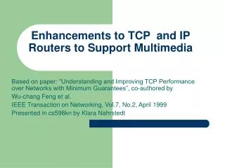
Forwarding engine - summarize • Sufficient to offer a simple, best-effort packets forwarding. • Additional functionality required of the next generation of routers (multicast, QoS differentiation, firewall filtering, etc.) • Needs to base the routing decision on more fields in the packets header.
IP Switching • Can used any higher level IP functionality. • Uses the concept of a flow(a sequence of packets that are treated identically by possibly complex routing function). • Uses an ATM switch as the switch fabric.
ATM as Switch Fabric • The 3 approaches that uses ATM as Switch Fabric are: • IP/ATM. • Cell Switch Router (CSR). • IP Switching.
ATM as Switch Fabric • Incoming flows are mapped onto ATM VC’s. • The IP Switch uses a protocol IFMP (RFC1953) to propagate the mapping between flow and VCI. • IP/ATM uses a pool of pre-established PVC’s. • CSR uses RSVP protocol (RFC1577)to propagate the mapping between flows and VCI’s.
Flow Classification • Flow classification operation is to select those flows that are to be switched in the ATM switch and those that should be forwarded in the forwarding engine. • Long duration flows - ATM switch. • Multicast - ATM switch. • Short duration flows - Forwarding engine.
IP Switch Controller IP Switch Controller Port C Port C Port 1 Port 1 Port 0 Port 0 Flow Classification (1)
Flow Classification (2) • For the flows selected for switching, a VC must be established. • IP Switching requires a protocol to distribute the association of flow and VCI label. • The task of cache lookup and packet labeling is propagated upstream to the edge of the network.
Flow Classification - summery • IP switch provides high speed routing by low level switching of flows. • It defines protocol to indicate these flows. • All flows are classified. • The forwarding engine is optimized for flow classification and for forwarding uncached packets.
IP Switch IP Switch Controller Default Forwarding by the IP Switch IP Switch Upstream direction Downstream direction IP Switch Controller Source Destination Default Default
Forwarding by the IP Switch IP Switch Controller Upstream direction Downstream direction Port C z IFMP Redirect (Flow ID,VPI/VCI=A,lifetime) Default Default VPI/VCI=A Port 1 Port 0
Forwarding by the IP Switch IP Switch Controller Upstream direction Downstream direction Port C IFMP Redirect (Flow ID,VPI/VCI=A,lifetime) IFMP Redirect (Flow ID,VPI/VCI=B,lifetime) Default Default VPI/VCI=A VPI/VCI=B Port 1 Port 0
General Switch Management Protocol (GSMP) • Simple master-slave protocol. • Switch controller - master. • ATM switch - slave. • Unreliable massage transport is assumed between controller and switch for speed and simplicity. • GSMP runs on a single well known virtual channel (VPI 0,VCI 15).
Ver Type Result Code Transaction Identifier GSMP Message Body Pad (0-47 octets) GSMP (1) • The most frequent messages (connection management) are small enough to be a single cell. GSMP Message Format
GSMP (2) • An adjacency protocol is used to: • Synchronize state across the control link. • Discover the identity of the entity of the far end of the link. • Detect when the far end is changed. • No GSMP massages may be sent across the link until adjacency has been established.
GSMP (3) • GSMP has five type of massages: • Configuration. • Connection management. • Port management. • Statistics. • Events.
Ipsilon Flow Management Protocol (IFMP) • Runs on a point to point link between two IP switches. • The purpose of IFMP is to inform the transmitting end of a link of the VCI that should be associated with a particular IP flow. • The VCI is selected by the receiving end of the link.
IFMP (1) • Two flow types has been defined: • port-pair flow (type 1) - source IP address,destination IP address,source port number,destination port number. • Host-pair flow (type 2) - source IP address,destination IP address. • An IFMP redirect message is sent upstream to inform the transmitter of the association between flow and VCI.
Flow Type Flow ID Lifetime Label Flow Identifier Ver IHL TOS TTL Protocol Ver IHL Rsrvd TTL Rsrvd Source IP Address Source IP Address Destination IP Address Destination IP Address Source Port Destination Port IFMP (2) IFMP Redirect MSG Flow type 1 - Identifier Flow type 2 - identifier
IFMP (3) • A lifetime field specified the length of time for witch this association of flow and VCI is valid. • The flow redirection must be refreshed. • Flow labeling process occurs independently an concurrently on each link. • The flow classification policy is consistent within an administrative domain.
IFMP (4) • When upstream and downstream links are both labeled for a given flow, that flow is switched directly trough the ATM switch. • When an IP switch accepts a redirection messages it also change the encapsulation. • It allows an IP switch to act as a simple based firewall.
Conclusion • The IP switch is an alternative architecture to the gigabit router. • It uses low level switching of flows. • It include a cooperative protocols. • Link by link basis decision. • All flows are classified. • It allows to support multicast, QoS, Simple firewall filtering.