Download
1 / 80
800 likes | 993 Vues
Applications of Image Motion Estimation I Mosaicing. Princeton University COS 429 Lecture Feb. 26, 2004. Harpreet S. Sawhney hsawhney@sarnoff.com. Visual Motion Estimation : Recapitulation. Plan. Explain optical flow equations Show inclusion of multiple constraints for solution

E N D
Applications of Image Motion Estimation IMosaicing Princeton University COS 429 Lecture Feb. 26, 2004 Harpreet S. Sawhney hsawhney@sarnoff.com
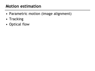
Plan • Explain optical flow equations • Show inclusion of multiple constraints for solution • Another way to solve is to use global parametric models
Brightness Constancy Assumption Model image transformation as : Brightness Constancy Optical Flow Corresponding Coordinate Reference Coordinate
How do we solve for the flow ? Use Taylor Series Expansion Image Gradient Convert constraint into an objective function
Optical Flow Constraint Equation At a Single Pixel Leads to Normal Flow
X Multiple Constraints in a Region
Solution • Observations: • A is a sum of outer products of the gradient vector • A is positive semi-definite • A is non-singular if two or more linearly independent • gradients are available • Singular value decomposition of A can be used to • compute a solution for u
Another way to provide unique solutionGlobal Parametric Models • u(p) is described using an affine transformation valid within the whole region R
Affine Motion Good approximation for : • Small motions • Small Camera rotations • Narrow field of view camera • When depth variation in the scene is small compared to the average depth and small motion • Affine camera images a planar scene
Affine Motion • Affine camera: • 3D Motion: • A 3D Plane:
Two More Ingredients for Success • Iterative solution through image warping • Linearization of the BCE is valid only when u(p) is small • Warping brings the second image “closer” to the reference • Coarse-to-fine motion estimation for estimating a wider range of image displacements • Coarse levels provide a convex function with unique local minima • Finer levels track the minima for a globally optimum solution
Image Warping • Express u(p) as: Target Image : Empty Source Image : Filled p
d(p) - Warper { R, T, d(p) } { H, e, k(p) } { dx(p), dy(p) } Coarse-to-fine Image Alignment : A Primer
Mosaics In Art…combine individual chips to create a big picture... Part of the Byzantine mosaic floor that has been preserved in the Church of Multiplication in Tabkha (near the Sea of Galilee). www.rtlsoft.com/mmmosaic
Image Mosaics • Chips are images. • May or may not be captured from known locations of the camera.
WHAT MAKES MOSAICING POSSIBBLE…the simplest geometry... Single Center of Projection for all Images Projection Surfaces Images COP
Planar Mosaic Construction 2 3 4 1 • Align Pairwise: 1:2, 2:3, 3:4, ... • Select a Reference Frame • Align all Images to the Reference Frame • Combine into a Single Mosaic Virtual Camera (Pan) Image Surface - Plane Projection - Perspective
Key Problem What Is the Mapping From Image Rays to the Mosaic Coordinates ? Rotations/Homographies Plane Projective Transformations Images COP
PYRAMID BASED COARSE-TO-FINE ALIGNMENT … a core technology ... • Coarse levels reduce search. • Models of image motion reduce modeling complexity. • Image warping allows model estimation without discrete feature extraction. • Model parameters are estimated using iterative non-linear optimization. • Coarse level parameters guide optimization at finer levels.
ITERATIVE REWEIGHTED SUM OF SQUARES • Given a solution at the mth iteration, find by solving : acts as a soft outlier rejecter :
PROGRESSIVE MODEL COMPLEXITY…combining real-time capture with accurate alignment... • Provide user feedbackby coarsely aligning incoming frames with a low order model • robust matching that covers a wide search range • achieve about 6-8 frames a sec. on a Pentium 200 • Use the coarse alignment parameters to seed the fine alignment • increase model complexity from similarity, to affine, to projective parameters • coarse-to-fine alignment for wide range of motions and managing computational complexity
VIDEO MOSAIC EXAMPLE Princeton Chapel Video Sequence 54 frames
Image Merging withLaplacian Pyramids Image 2 Image 1 2 1 Combined Seamless Image
1D vs. 2D SCANNING • 1D : The topology of frames is a ribbon or a string. Frames overlap only with their temporal neighbors. (A 300x332 mosaic captured by mosaicing a 1D sequence of 6 frames) • 2D : The topology of frames is a 2D graph • Frames overlap with neighbors on many • sides
1D vs. 2D SCANNING The 1D scan scaled by 2 to 600x692 A 2D scanned mosaic of size 600x692
CHOICE OF 1D/2D MANIFOLD Cylinder Cone Plane Sphere Arbitrary
THE “DESMILEY” ALGORITHM • Compute 2D rotation and translation between successive frames • Compute L by intersecting central lines of each frame • Fill each pixel [l y] in the rectified planar mosaic by mapping it to the appropriate video frame
2D MOSAICING THROUGH TOPOLOGY INFERENCE&LOCAL TO GLOBAL ALIGNMENT… automatic solution to two key problems ... • Inference of 2D neighborhood relations (topology) between frames • Input video just provides a temporal 1D ordering of frames • Need to infer 2D neighborhood relations so that local constraints may be setup between pairs of frames • Globally consistent alignment and mosaic creation • Choose appropriate alignment model • Local constraints incorporated in a global optimization
PROBLEM FORMULATION Given an arbitrary scan of a scene Create a globally aligned mosaic by minimizing Like an MDL measure : Create a compact appearance while being geometrically consistent
ERROR MEASURE where
ALGORITHMIC APPROACH From a 1D ordered collection of frames to A Globally consistent set of alignment parameters Iterate through • 1. Graph Topology Determination • Given: pose of all frames • Establish neighborhood relations min(Area of Mosaic) • Graph G • 2. Local Pairwise Alignment • Given: G • Quality measure validates hypothesized arcs • Provides pairwise constraints • 3. Globally Consistent Alignment • Given: pairwise constraints • Compute reference-to-frame pose parameters min
GRAPH TOPOLOGY DETERMINATION Dij dij • Given: Current estimate of pose* • Lay out each frame on the 2D manifold (plane, sphere, etc.) • Hypothesize new neighbors based on • proximity • predictability of relative pose • non redundancy w.r.t. current G • Specifically, try arc (i,j) if Normalized Euclidean dist dij << Path distance Dij • Validatehypothesis by local registration • Add arc to G if good quality registration * Initialize using low order frame-to-frame mosaic algorithm on a plane
LOCAL COARSE & FINE ALIGNMENT • Given: a frame pair to be registered • Coarse alignment • Low order parametric model e.g. shift, or 2D R & T • Majority consensus among subimage estimates • Fine alignment [Bergen, ECCV 92] • Coarse to fine over Laplacian pyramid • Progressive model complexity, up to projective • Incrementally adjust motion parameters to minimize SSD • Quality measure • Normalized correlation helps reject invalid registrations
ui uj Eij GLOBALLY CONSISTENT ALIGNMENT • Given: arcs ij in graph G of neighbors • The local alignment parameters, Qij, help establish feature correspondence between i and j • If uil and ujlare corresponding points in frames i,j, then • Incrementally adjust poses Pi to minimize
SPECIFIC EXAMPLES : 1. PLANAR MOSAICS • Mosaic to frame transformation model: • Local Registration • Coarse 2D translation & fine 2D projective alignment • Topology : Neighborhood graph defined over a plane • Initial graph topology computed with the 2D T estimates • Iterative refinement using arcs based on projective alignment • Global Alignment Pair Wise Alignment Error Minimum Distortion Error
PLANAR TOPOLOGY EVOLUTION Whiteboard Video Sequence 75 frames