Download
1 / 10
100 likes | 227 Vues
Chapter 4B: The Processor, Part B-2. Read Section 4.7. Adapted from Slides by Prof. Mary Jane Irwin, Penn State University And Slides Supplied by the textbook publisher . DM. DM. Reg. Reg. Reg. Reg. IM. IM. ALU. ALU. Memory-to-Memory Copies Data Hazard.

E N D
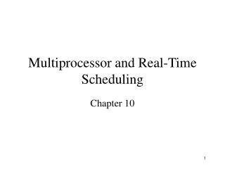
Chapter 4B: The Processor, Part B-2 Read Section 4.7 Adapted from Slides by Prof. Mary Jane Irwin, Penn State University And Slides Supplied by the textbook publisher
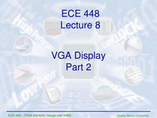
DM DM Reg Reg Reg Reg IM IM ALU ALU Memory-to-Memory Copies Data Hazard • load immediately followed by store (memory-to-memory copy) • What could be done? CC0 CC1 CC2 CC3 CC4 CC6 CC7 CC8 CC5 I n s t r. O r d e r 1 lw$1,4($2) The Data Hazard: Instruction 1 loads register 1 in clock cycle 4 instruction 2 needs the NEW data of register 1 during clock cycle 2 2 sw$1,4($3)
DM DM Reg Reg Reg Reg stall stall IM IM ALU ALU Memory-to-Memory Copies Data Hazard • Can fix data hazard by waiting – stalling CC0 CC1 CC2 CC3 CC4 CC6 CC7 CC8 CC5 I n s t r. O r d e r 1 lw$1,4($2) Instruction 1 writes data in register 1 in first half of cycle 4 instruction 2 reads data from register 1 in second half of cycle 4 The data hazard is resolved! (BUT impacts CPI) 2 sw$1,4($3)
DM DM Reg Reg Reg Reg IM IM ALU ALU Memory-to-Memory Copies • For loads immediately followed by stores (memory-to-memory copies) can avoid a stall by adding forwarding hardware from the MEM/WB register to the data memory input. • Would need to add a Forward Unit and a mux to the MEM stage CC0 CC1 CC2 CC3 CC4 CC6 CC7 CC8 CC5 I n s t r. O r d e r lw $1,4($2) sw $1,4($3)
DM DM Reg Reg Reg Reg IM IM ALU ALU Add-to-store hazard • What if lw was replaced with add $1, - is forwarding still needed? From where, to where? CC0 CC1 CC2 CC3 CC4 CC6 CC7 CC8 CC5 I n s t r. O r d e r add $1, sw $1,4($3)
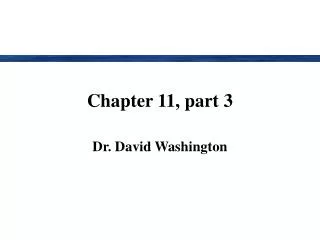
DM DM DM DM DM Reg Reg Reg Reg Reg Reg Reg Reg Reg Reg stall IM IM IM IM IM IM ALU ALU ALU ALU ALU ALU and $6,$1,$7 and $6,$1,$7 or $8,$1,$9 or $8,$1,$9 xor $4,$1,$5 xor $4,$1,$5 DM Reg Forwarding with Load-use Data Hazards Before stalling, whenlw instruction was in the EX stage, the Useinstructionn was in the ID stage CC0 CC1 CC2 CC3 CC4 CC6 CC7 CC8 CC5 lw$1,4($2) I n s t r. O r d e r sub $4,$1,$5 sub $4,$1,$5 • Will still need one stall cycle even with forwarding
Load-use Hazard Detection Unit • Need a Hazard Detection Unit in the ID stage that inserts a stall between the load and its use Whenlw instruction is in the EX stage, the load-use instruction is in the ID stage ID Hazard Detection Unit: if (ID/EX.MemRead and ((ID/EX.RegisterRt = IF/ID.RegisterRs) or (ID/EX.RegisterRt = IF/ID.RegisterRt))) stall the pipeline • The first line tests to see if the instruction now in the EX stage is a lw; the next two lines check to see if the target register of the lw(ID/EX.RegisterRt) matches either Rs or Rtregister of the instruction in the ID stage (the load-use instruction) • After this one cycle stall, the forwarding logic can handle the remaining data hazards
Hazard (Detection)/Stall Hardware • Along with the ID Hazard Detection Unit, we have to implement the stall. This means: • Prevent the instructions in the IF and ID stages from progressing down the pipeline – done by preventing the PC register and the IF/ID pipeline register from changing • The ID Hazard Detection Unit controls the writing of the PC and IF/ID registers through the use of the signals (PC.write) (IF/ID.write) • Insert a “bubble” between the lw instruction (in the EX stage) and the “load-use” instruction (in the ID stage) (i.e., insert a noop in the execution stream) • Set the control bits in the EX, MEM, and WB control fields of the ID/EX pipeline register to 0 (noop). The ID Hazard Unit controls the mux that chooses between the real control values and the 0’s.
Hazard (Detection)/Stall Hardware (cont.) • Let the lw instruction and the instructions after it in the pipeline (before it in the code) proceed normally down the pipeline
ID/EX.MemRead 0 ID/EX.RegisterRt Adding the Hazard/Stall Hardware PCSrc Hazard Unit ID/EX IF/ID.Write EX/MEM 0 PC.Write IF/ID 1 Control Add MEM/WB Branch Add 4 Shift left 2 Read Addr 1 Instruction Memory Read Data 1 Data Memory Read Addr 2 Read Address Register File PC Read Data Address Write Addr ALU Read Data 2 Write Data Write Data ALU cntrl 16 32 Sign Extend IF/ID.RegisterRs and IF/ID.RegisterRt Forward Unit