Download
1 / 10
130 likes | 302 Vues
Evaporative emission system. GROUP 4 AZIZ PULUNGAN BIN JUMAIRI 01DAD10F2035 IIZHARUDDIN SHAH BIN MUZAFFAR 01DAD10F2037 RICHARD SELVARAJAH 01DAD10F2036 NURHAFIZ BIN ISHAK 01DAD10F2044 IHSANUDDIN BIN SUHAINI 01DAD10F2051. EVAPORATIVE EMISSION CONTROL SYSTEM

E N D
Evaporative emission system GROUP 4 AZIZ PULUNGAN BIN JUMAIRI 01DAD10F2035 IIZHARUDDIN SHAH BIN MUZAFFAR 01DAD10F2037 RICHARD SELVARAJAH 01DAD10F2036 NURHAFIZ BIN ISHAK 01DAD10F2044 IHSANUDDIN BIN SUHAINI 01DAD10F2051
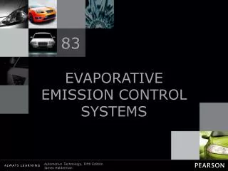
EVAPORATIVE EMISSION CONTROL SYSTEM • The Evaporative Emission Control (EVAP) system is designed to store • and dispose of fuel vapors normally created in the fuel system; thereby, preventing its escape to the atmosphere • Approximately 20% of all hydrocarbon (HC) emissions from the automobile originate from evaporative sources. • The EVAP system is a fully closed system designed to maintain stable fuel tank pressures without allowing fuel vapors to escape to the atmosphere.
TOYOTA VEHICLES USE TWO DIFFERENT TYPES OF EVAPORATIVE EMISSION CONTROL SYSTEMS: • • ECM controlled EVAP systems • Non-ECM controlled EVAP systems • Non-ECM controlled EVAP systems use solely mechanical means to collect and purge stored fuel vapors. • these systems use a ported vacuum purge port and a Thermo Vacuum Valve (TVV) to prohibit cold engine operation. • • ECM controlled EVAP systems uses a manifold vacuum purge source in conjunction with a duty cycled Vacuum Switching Valve (VSV). • This type of EVAP system has the ability to provide more precise control of purge flow volume and inhibit operation. • Non-ECM controlled EVAP systems typically use the following components: • • Fuel tank cap (with vacuum check valve) • • Charcoal canister (with vacuum & pressure check valves) • • Thermo Vacuum Valve (TVV)
EVAP SYSTEM OPERATION Under some conditions, the fuel tank operates under a slight pressure to reduce the possibility of pump cavitation due to fuel vaporization. Pressure is created by unused fuel returning to the tank and is maintained by check valve #2 in the charcoal canister and the check valve in the fuel tank cap. Under other conditions, as fuel is drawn from the tank, a vacuum can be created in the tank causing it to collapse. This is prevented by allowing atmospheric pressure to enter the tank through check valve #3 in the charcoal canister or the fuel tank cap check valve. The EVAP system is designed to limit maximum vacuum and pressure in the fuel tank in this manner. When the engine is running, stored fuel vapors are purged from the canister whenever the throttle has opened past the purge port (port P) and coolant temperature is above a certain point (usually around 129' F). Fuel vapors flow from the high pressure area in the canister, past check valve #1 in the canister, through the Thermo Vacuum Valve (TVV), to the low pressure area in the throttle body. Atmospheric pressure is allowed into the canister through a filter located on the bottom of the canister. This ensures that purge flow is constantly maintained whenever purge vacuum is applied to the canister. When coolant temperature falls below a certain point (usually around 95’F), the TVV prevents purge from taking place by blocking the vacuum signal to check valve #1.
THE END… THANK YOU….