Download
1 / 14
140 likes | 281 Vues
GLD Surface Assembly. Y. Sugimoto KEK 2006.08.15. Outline. Weight of GLD components GLD assembly scenarios Scenario 1: Assemble mostly underground Scenario 2: CMS style Scenario 3: Something between 1 and 2. Return Yoke Barrel (Baseline design) Leakage field < 50 G @10m 50-150 t/slab

E N D
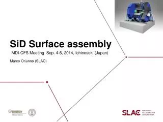
GLD Surface Assembly Y. Sugimoto KEK 2006.08.15
Outline • Weight of GLD components • GLD assembly scenarios • Scenario 1: Assemble mostly underground • Scenario 2: CMS style • Scenario 3: Something between 1 and 2
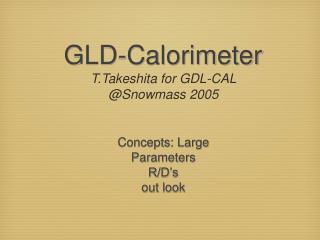
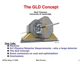
Return Yoke Barrel (Baseline design) Leakage field < 50 G @10m 50-150 t/slab 700 t/sector(30 deg) 8300 t total 15 OKU\ (1 OKU\ ~ 0.9 M$) Barrel (Previous design) Leakage field = 90 G @10m 50-72 t/slab 540 t/sector 6500 t total 12 OKU\ Endcap (Baseline design) 20-370 t/slab(180 deg) 2100 t/180 deg 4160 t/side 8300 t total 15 OKU\ Endcap (Previous design) 20-160 t/slab 1500 t/180 deg 3000 t/side 6000 t total 11 OKU\ Weight of GLD components Relaxing the requirement for leakage field would reduce cost for return-yoke, exp.hall, etc.
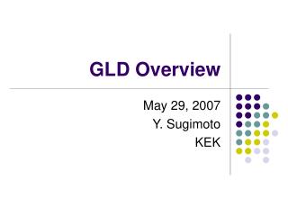
Calorimeter Barrel (central) 1100 t (HCAL) 220 t (ECAL) Barrel (edge) 235 t/side 470 t total Barrel (total) 1800 t Solenoid+Cryostat 270 t Endcap 220 t/side (HCAL) 60 t/side (ECAL) 280 t/side (H+E) 560 t total Weight of GLD components
Barrel (edge) Barrel (central) Endcap
Key milestones • Detector assembly building ready: t0+3y • Detector hall ready for detector: t0+4y11m from Martin Gastal’s talk at VLCW2006
Scenario 1 • If the cavern gets ready for detector at t0+4y11m, only 2y+1m is left before machine commissioning, which seems too short • BCD assumes 80 t crane in the cavern. This is too little for GLD (Msolenoid = 270 t) • So, we need CCR anyway
Scenario 2: CMS style • Surface assembly hall has 2000t non-traveling crane • Detector is segmented into several large pieces < 2000t • So, each segment of the detector has to crawl to the loading area by itself • Then, CMS-like segmentation (divide the barrel into wheels) would be the only solution • Possible problems in this method; • Can we get enough mechanical precision in assembly ? • Cryostat is supported only at the center. Mechanical strength to support 1800t CAL is not clear • Gaps for cables between wheels Leakage field ? • Surface assembly hall gets ready at t0+3y. It would be impossible to assemble and test the whole detector in 1y11m. • We need larger access shaft (diameter>20m)
Scenario 3: Our proposal • Each of the surface assembly hall and the underground experimental hall is equipped with a relatively large capacity (>400t) overhead “traveling” crane • Detector is assembled on surface up to few tens of segments lighter than the crane capacity. For example, • Barrel Yoke + muon detector: 12(f) x 2(r) = 24 pieces (~350t/piece) • End Yoke + muon detector: 2(side) x 4(f) x 3(z) =24 pieces (~350t/piece) • Barrel CAL: 7 rings (260t/ring) • Endcap CAL: 2 (side) x 2 (f) = 4 pieces (140t/piece) • Solenoid, TPC, FCAL, BCAL, and inner Si trackers are installed individually • These segments are lowered to the cavern and assembled to form a complete detector
Comments on Scenario 3 • Since muon detectors are installed in the surface assembly hall, the endcaps do not have to fully open. The wall only 12m from the beam line is acceptable. • If the barrel part can move both along and normal to the beam line (probably possible by using air-pallet), the width of the experimental hall (32 m in the baseline design) can be somewhat smaller. (see next slides) • Because less assembly work is done in the experimental hall than the Scenario-1, the size of the cavern could be still smaller • Detailed assembly procedure will depend on the machine commissioning scenario • In addition to the surface assembly hall, a large-area warehouse would be necessary to store many pre-assembled detector segments. No large-capacity crane is necessary in this warehouse if we use air-pallets to move the detector segments.
Conclusion • If the cavern gets ready for detector at t0+4y11m, only 2y+1m is left before machine commissioning. This period seems too short to assemble the detector totally underground. • We absolutely need a large assembly hall on surface • It is not clear for us whether we can assemble the detector exactly like CMS or not • We would like to consider the assembly scenario in which the detector is segmented into smaller pieces than that in the CMS assembly scenario • In that case, we need >400t overhead traveling crane in both the surface assembly hall and the underground experimental hall • In addition to the surface assembly hall, a large-area warehouse would be necessary to store the pre-assembled segments • We have to investigate more to determine the necessary size of the surface assembly hall and the underground experimental hall in our assembly scenario