Download
1 / 48
480 likes | 644 Vues
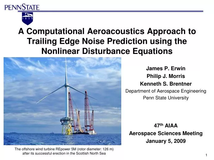
A Computational Aeroacoustics Approach to Trailing Edge Noise Prediction using the Nonlinear Disturbance Equations. James P. Erwin Philip J. Morris Kenneth S. Brentner Department of Aerospace Engineering Penn State University 47 th AIAA Aerospace Sciences Meeting January 5, 2009.

E N D
A Computational Aeroacoustics Approach to Trailing Edge Noise Prediction using the Nonlinear Disturbance Equations James P. Erwin Philip J. Morris Kenneth S. Brentner Department of Aerospace Engineering Penn State University 47th AIAA Aerospace Sciences Meeting January 5, 2009 The offshore wind turbine REpower 5M (rotor diameter: 126 m) after its successful erection in the Scottish North Sea
Outline • Wind turbine acoustics • New trailing edge noise prediction method • The Nonlinear Disturbance Equations (NLDE) • NLDE code • validation • circular cylinder and airfoil test cases • Summary and future work suggestions
Acoustic Issues for Wind Turbines Low blade passage frequency Low frequency sound is relatively unaffected by atmospheric attenuation – can propagate long distances Blade passage frequency below threshold of human hearing ~15Hz Broadband noise prediction is critical Broadband noise is probably the dominant noise source (especially when modulated at blade passage frequency) Scale of large wind turbines leads to broadband noise at relatively low frequencies that also propagates long distances Unsteady flow environment Unsteady wind creates excess noise Tower and terrain wake Nonuniform inflow due to atmospheric boundary layer
Broadband Noise –Self Noise Sources Current methods to predict broadband noise is semi-empirical. Ref. Brook, Pope, and Marcolini, 1989
Acoustic Issues for Wind Turbines Large-Eddy Simulation (LES) of a complete wind turbine and all noise sources not feasible in the near future (especially for design purposes) Direct computation of broadband noise sources is possible – if focus is only small noise generating regions of flow Must divide the CAA problem into sub-parts which can each be solved in the most efficient way possible
Outline • Wind turbine acoustics • New trailing edge noise prediction method • The Nonlinear Disturbance Equations (NLDE) • NLDE code • validation • circular cylinder and airfoil test cases • Summary and future work suggestions
Trailing Edge Noise Prediction Method • 1. Obtain mean flow for entire blade • - RANS solution for “quick” estimate of mean flow • Solve the NLDE on the trailing edge* portion only • - Use a fine trailing edge grid • - Solve for time accurate pressure time history • 3. Noise prediction from NLDE solution • - PSU-WOPWOP – Penn State’s noise prediction software • - Uses NLDE solution to calculate broadband noise and propagate to observers RANS * Focus here is on the TE but these tools will also work for the LE and blade tip (or other sources)
Outline • Wind turbine acoustics • New trailing edge noise prediction method • The Nonlinear Disturbance Equations (NLDE) • NLDE code • validation • circular cylinder and airfoil test cases • Summary and future work suggestions
Nonlinear Disturbance Equations(NLDE) Multi-level hybrid approach Use the algorithm best suited to the computation Steady RANS for mean flow (calculation in entire domain on relatively coarse grid) Time accurate solution for disturbances (calculation in limited region on a refined grid) Present formulation based on compressible Navier-Stokes equations (ideal for acoustic simulations) Basic flow from rotating blade simulations OVERFLOW2 Resolved perturbations – simulated using time accurate calculations on refined grid NLDE Sub-grid scale perturbations modeled
Previous Applications Turbulent boundary layer: T. Chyczewski, P. Morris, and L. Long, (2000) AIAA Paper 2000-2007 Bluff body flows: R. P. Hansen, L. N. Long, and P. J. Morris, (2000) AIAA Paper 2000-1981 High speed jet noise: Morris, Long, Scheidegger & Boluriaan, (2002) Int. Journal Aeroacoustics, 1(1) Steady and pulsating channel flow, low pressure turbine blade: Labourasse & Sagaut (2003) J. Comp. Phys., 182 (L&S, 2003)
Nonlinear Disturbance Equations The traditional compressible Navier Stokes equations can be written as (1D for simplicity) The NLDE decomposes this into a mean flow and perturbation flow Since we are solving for the perturbation quantities only, NOTE: no subscript ( )0 or prime ( )ʹ implies an instantaneous quantity
Nonlinear Disturbance Equations The flux vector F is updated at every time step The time rate of change of the mean flow is zero (steady mean flow) Initial condition?
Outline • Wind turbine acoustics • New trailing edge noise prediction method • The Nonlinear Disturbance Equations (NLDE) • NLDE code • validation • circular cylinder and airfoil test cases • Summary and future work suggestions
NLDE Code • Code features: • Compressible, 3-D structured grid Navier-Stokes solver • Fortran 90 language • MPI (Message Passing Interface) parallel code • Code structure allows for easy addition and removal of features • Boundary conditions tailored for CAA • 4th order accurate 5 stage LDDRK time integration [10] • Low-Dissipation and Dispersion Runge Kutta • 4th order accurate DRP finite differencing [11] • Dispersion-Relation-Preserving • Explicit low pass filtering [12]
Code Validation – 2-D Gaussian Pulse Mach 0.5 background flow (rightward) • Mach 0.0 and 0.5 background flow • 201 x 201 grid • No artificial damping • No low pass filtering Initial condition
Code Validation – 2-D Gaussian Pulse t = 0.02 seconds t = 0.06 seconds Mach 0.5 background flow t = 0.2 seconds t = 0.4 seconds
Code Validation – 3-D Gaussian Pulse • 61 x 61 x 61 Cartesian grid • Zero background flow • No artificial damping • No low pass filtering Initial acoustic pressure pulse
Code Validation – Adiabatic Wall • Tam and Dong, 1993 [14] • Testing adiabatic wall boundary conditions Mach 0.5 background flow Tam and Dong pressure contours Equivalent NLDE code contours
Outline • Wind turbine acoustics • New trailing edge noise prediction method • The Nonlinear Disturbance Equations (NLDE) • NLDE code • validation • circular cylinder and airfoil test cases • Summary and future work suggestions
Circular Cylinder Flow – 2-D Coarse grid 100 points circumferentially 150 points radially 5% wall spacing Fine grid 301 points circumferentially 65 points radially 0.5% wall spacing Hyperbolic tangent stretching
Circular Cylinder Flow – 2-D • Red = 90,000 (based on diameter) • Uniform Mach 0.2 (rightward) mean flow • Radiation condition applied at far field boundaries • Instantaneous no slip condition at surface is enforced by • specifying u´ = -u0, v´ = -v0, and w´ = -w0 Instantaneous flow (shortly after no slip condition is applied) Mean flow (initial condition)
Circular Cylinder Flow – 2-D coarse cylinder grid fine cylinder grid
Circular Cylinder Flow – 2-D f – shedding frequency L – length scale (diameter) U – flow velocity .025 .030 .035 .040 Time (seconds)
Circular Cylinder Flow – 2-D Acoustic data surfaces provide PSU-WOPWOP with ρ,ρu,ρv,ρw,p´ Acoustic data surfaces can be placed anywhere in the flow field but they must enclose the body of interest NLDE grid acoustic data surface (ADS)
Circular Cylinder Flow – 2-D PSU-WOPWOP calculates the acoustic pressure and sound pressure level for any combination of observer positions
Circular Cylinder Flow – 2-D Fine grid Mach 0.2 90° observer directivity
Airfoil Blade Sections • Apply tools developed previously to real airfoil blade sections • Initiate the simulation with assumed uniform mean flow • Study the noise characteristics of different trailing edges • NACA series airfoils • Blade Systems Design Study (BSDS) rotor blade section • Increase resolution in areas of interest • Trailing edges • Also leading edges, boundary layers, etc
NACA 0012 Airfoil • 0.1% trailing edge thickness (relative to chord) • Mach 0.2 (Rec = 4.5 million), 0° aoa • Representative of the tip of a 9 meter turbine blade
NACA 0012 Airfoil Laminar Boundary Layer – Vortex Shedding Noise
NACA 0012 Airfoil Observers placed on a circle with a radius of 5 chords centered at TE directivity 90° observer
BSDS Blade Sections • Blade Systems Design Study (BSDS) wind turbine rotor • Grid provided by Sandia National Laboratories • “Flatback” airfoil design for structural strength at root of blade • How does this affect airfoil performance and noise? 5.5% trailing edge thickness (relative to chord)
BSDS Blade Sections directivity 90° observer
Outline • Wind turbine acoustics • New trailing edge noise prediction method • The Nonlinear Disturbance Equations (NLDE) • NLDE code • validation • circular cylinder and airfoil test cases • Summary and future work suggestions
Summary New CAA method for trailing edge noise prediction NLDE flow solver is based on first principles methods for broadband noise prediction Coupled with OVERFLOW2 and PSU-WOPWOP NLDE code Validated with exact solutions Tested with circular cylinder flow and first airfoil attempts PSU-WOPWOP support Noise prediction of any area of interest Acquiring good RANS solution is not critical The NLDE solution provides correction to mean flow (faster convergence with better RANS solution) – using uniform mean flow for code development
Future work suggestions Triggering flow unsteadiness for realistic TBL-TE noise calculations Same issue with LES or DES simulations (L&S, 2003) used random, divergence free initialization Use of recycling in initial upstream region Accurate turbulence characteristics needed for accurate broadband noise prediction Multistep method to decrease runtime of compressible viscous calculations Airfoil calculations take days to simulate sufficient time length Compare noise of different blade sections Develop thorough and well defined test cases to properly analyze blade sections of interest, like the flatback BSDS sections.
Acknowledgement This research was supported by Sandia National Laboratories, Purchase Order No. A0342 677302, Dale Berg and Matthew Barone, Technical Monitors.
Review:Nonlinear Disturbance Equations • 1. What are they? • - The complete set of compressible Navier-Stokes • equations separated into an assumed mean flow component and a perturbationcomponent • - The NLDE solve for the perturbation component about an estimated mean • 2. What are the benefits? • - Resolve different flow scales • - Allows simple application of detailed CAA boundary conditions • - Mean flow is assumed to already satisfy BCs • - NLDE equations only need to be solved in small region of • flow that generates noise • 3. How are they solved? • - Same way as the traditional N-S equations • - Mean flow is treated as a known source term • - Only the perturbation variables are numerically integrated for a time-accurate solutionof acoustic pressure
Code Validation – 2-D Gaussian Pulse Mach 0.0 and 0.5 background flow 201 x 201 grid No artificial damping No low pass filtering
Code Validation – 2-D Gaussian Pulse Mach 0.5 background flow (rightward)
Circular Cylinder Flow – 2-D coarse cylinder grid
Circular Cylinder Flow – 2-D fine cylinder grid
NACA 0012 airfoil Laminar Boundary Layer – Vortex Shedding Noise