Download
1 / 50
620 likes | 1.23k Vues
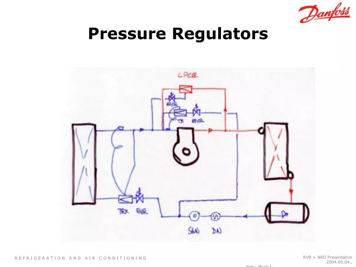
Pressure Regulators. Pressure Regulators Overview. CONDENSER PRESSURE REGULATORS EVAPORATOR PRESSURE REGULATORS CRANKCASE PRESSURE REGULATORS HOTGAS BY-PASS REGULATORS Direct feed of hot gas Use of Liquid/Vapour mix. Some Functions of Regulators.

E N D
Pressure Regulators KVR + NRD Presentation 2004.05.04., Jbm - Page1
Pressure RegulatorsOverview • CONDENSER PRESSURE REGULATORS • EVAPORATOR PRESSURE REGULATORS • CRANKCASE PRESSURE REGULATORS • HOTGAS BY-PASS REGULATORS • Direct feed of hot gas • Use of Liquid/Vapour mix KVR + NRD Presentation 2004.05.04., Jbm - Page2
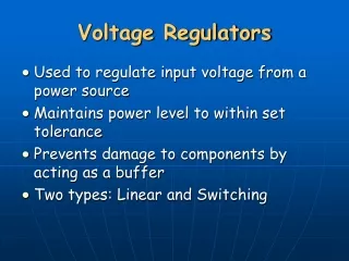
Some Functions of Regulators • Maintain required temperatures through control of pressure • Maintain pressure to components that are within operating envelopes • Ensure adequate pressure differential across metering devices in all ambients KVR + NRD Presentation 2004.05.04., Jbm - Page3
Condenser Pressure Regulators (CPR) Application Information The main purpose of a condenser pressure regulator is to maintain sufficient pressure at the TEV during low ambient (Outdoor) temperatures KVR + NRD Presentation 2004.05.04., Jbm - Page4
Location of CPR Condenser Used in the liquid line before the receiver KVR + NRD Presentation 2004.05.04., Jbm - Page5
Condenser Pressure Regulator Condensing Temperature = 110 Fahrenheit 90 degree Fahrenheit Air Inlet Temperature • Condensers are designed for a certain difference between the outside ambient temperature and the condensing temperature • Because the condenser must be able to reject heat even at high loads, the condenser must be large enough to reject this heat even when it is hot outside i.e. 90F KVR + NRD Presentation 2004.05.04., Jbm - Page6
Condenser Pressure Regulator When the outdoor temperature is lower, the condenser acts like it is a lot larger Temperature = 90F Temperature = 20F KVR + NRD Presentation 2004.05.04., Jbm - Page7
Condenser Pressure Regulator • When the condenser effectively becomes larger, the condensing pressure can drop substantially ,causing the TEV to operate erratically • The CPR acts by reducing the area available for heat rejection, effectively making the condenser smaller KVR + NRD Presentation 2004.05.04., Jbm - Page8
Condenser Pressure Regulator This the way the condenser behaves when liquid is backed up in it Only a portion of it can reject heat • The CPR accomplishes this by backing up the liquid in the condenser, using up free volume • The condenser then has a smaller area available to reject heat from the refrigerant KVR + NRD Presentation 2004.05.04., Jbm - Page9
Reduction in Latent Heat Capacity • If the coil is full of liquid, then the majority of the coil is only capable of sensible heat removal • This can reduce the capacity of the condenser by 300% Hot discharge gas inlet Sub-cooled liquid outlet KVR + NRD Presentation 2004.05.04., Jbm - Page10
superheating vapor 212 °F boiling water (liquid + vapor) heating water (liquid) Heat Energy - Enthalpy Enthalpy is the heat in BTUs per pound added to or removed from a substance, in this case water. Temperature 970 BTU/lb Heat (Energy) Enthalpy 180 BTU/lb KVR + NRD Presentation 2004.05.04., Jbm - Page11
CPR Functionality • The CPR closes on a fall in inlet pressure and opens on a rise in inlet pressure • The regulator is in turn set to operate over a given pressure range or Proportional band (P-band) with the opening pressure controlled by a chosen setting Capacity in % 100 75 50 25 psi 150 375 225 75 300 Factory setting P-band KVR + NRD Presentation 2004.05.04., Jbm - Page12
Relation of Capacity and P-band Capacity in % 100 75 Below are the values between the start of the valve opening and the valve being fully open 50 25 psi 75 150 225 300 P-band Factory setting KVR + NRD Presentation 2004.05.04., Jbm - Page13
Relation of Capacity and P-band Capacity in % 100 By subtracting the value of the opening pressure from the pressure @ fully open we arrive at the P-band 75 50 25 psi 75 150 225 300 P-band Factory setting KVR + NRD Presentation 2004.05.04., Jbm - Page14
Relation of Capacity and P-band Capacity in % 100 225 -150 = 75 psi The P-band is 75psi 75 50 25 psi 75 150 225 300 P-band Factory setting KVR + NRD Presentation 2004.05.04., Jbm - Page15
Relation between Capacity and Offset Capacity in % 100 75 Offset is the permissible difference between the operating pressure and the minimum pressure allowed. 50 25 psi 75 150 225 300 Factory setting Offset KVR + NRD Presentation 2004.05.04., Jbm - Page16
Relation between Capacity and Offset Capacity in % 100 75 In this example the operating pressure is 175 psi and the minimum pressure desired is 155 psi 50 25 psi 75 150 225 300 Factory setting Offset KVR + NRD Presentation 2004.05.04., Jbm - Page17
Use of Pressure Differential Valve -10 F with ambient air movement • Under very low ambient conditions, even back filling the condenser with liquid may not be adequate to maintain sufficient condensing pressure KVR + NRD Presentation 2004.05.04., Jbm - Page18
Differential Pressure Valve (DPV) The DPV uses a pressure differential to inject hot gas into the receiver to boost it’s pressure It opens when the pressure difference between the compressor discharge and the receiver is greater than the spring pressure holding the valve closed KVR + NRD Presentation 2004.05.04., Jbm - Page19
Differential Pressure Valve (DPV) A pressure differential of 20 psi will begin to open the DPV. It will inject hot gas into the receiver to boost it’s pressure. The valve will be 100% open when the differential pressure is 43psi. KVR + NRD Presentation 2004.05.04., Jbm - Page20
Location of CPR Condenser Hot gas is injected directly into the receiver KVR + NRD Presentation 2004.05.04., Jbm - Page21
SIZING THE KVR + NRD Conditions Refrigerant R-22 Capacity 72 000 BTU/hr Application Liquid line Desired Pressure drop 3 psi Evaporating temp. 20 F Condensing temp. +110F Liquid temp. +100F Connection KVR ½” flare NRD ½” solder KVR + NRD Presentation 2004.05.04., Jbm - Page22
Using the Application Guide • The capacity chart is based on rated capacities which assume certain conditions • In reality, the conditions are likely to be different and these differences need to be taken into consideration KVR + NRD Presentation 2004.05.04., Jbm - Page23
Using the Application Guide • The actual required capacity must be determined by using a correction factor for actual evaporating temp • = .97 X 82 000 = 79 540 BTU/hr = ~6.6 tons KVR + NRD Presentation 2004.05.04., Jbm - Page24
Using the Application Guide • The selection is made by locating the correct condensing temperature and the desired pressure drop across the valve and then picking the corrected capacity from the table KVR + NRD Presentation 2004.05.04., Jbm - Page25
Using the Application Guide • The final code number selection is determined by the family model that fits the connection requirements • In this example it is the 034L0091 with 1/2” flare connetions KVR + NRD Presentation 2004.05.04., Jbm - Page26
KVR & NRD Summary The KVR & NRD maintain sufficient condensing pressure during low loads and low ambient conditions They help to maintain a sufficient pressure differential across the TXV so it reliably controls according to it’s specifications KVR + NRD Presentation 2004.05.04., Jbm - Page27
Crankcase Pressure Regulators KVR + NRD Presentation 2004.05.04., Jbm - Page28
Crankcase Pressure Regulators • The KVL limits the amount of refrigerant returning back to the compressor • It is primarily used with low temperature compressors as they are designed for low density suction gas Evaporator KVR + NRD Presentation 2004.05.04., Jbm - Page29
Crankcase Pressure Regulators • During high loads, the returning gas can be at a high pressure and density and can damage the compressor motor • The KVL will close on a rise in inlet pressure, limiting the amount of refrigerant that returns to the compressor KVR + NRD Presentation 2004.05.04., Jbm - Page30
Crankcase Pressure Regulator Selection • Below are conditions from a system that we can use to make an example selection • System capacity is 8000 btu/hr or .65 tons • Refrigerant R404a • Suction temperature is -10F • Liquid temperature is 110F • Desired pressure drop across valve is 3 psi • Maximum suction pressure is 40 psi • Connection size is 7/8 sweat KVR + NRD Presentation 2004.05.04., Jbm - Page31
Crankcase Pressure Regulator Selection Tons • The capacities given in this code number table is based on certain assumptions about the conditions of the system (rated conditions) • Actual system conditions may be very different so the table capacities must not be used to make a selection KVR + NRD Presentation 2004.05.04., Jbm - Page32
Crankcase Pressure Regulator Selection • Below are the steps that we need to take to make a selection • Does this capacity exceed the required capacity? • If yes, then choose the code number for the valve from the code number selection table based on the size and type of connections required • If not, then go down to the next size of valves and repeat the process KVR + NRD Presentation 2004.05.04., Jbm - Page33
Crankcase Pressure Regulator Selection • Here we see the correction table that corrects for the temperature of the liquid ahead of the TXV • If the liquid temperature is different than 100F, then we need to use the appropriate conversion factor to correct the system capacity KVR + NRD Presentation 2004.05.04., Jbm - Page34
Crankcase Pressure Regulator Selection • To correct the system capacity, we multiply this capacity by the correction factor • Corrected capacity is .65 tons x 1.10 = .72 tons • .72 tons is the capacity we use to make a selection from the capacity table KVR + NRD Presentation 2004.05.04., Jbm - Page35
Crankcase Pressure Regulator Selection Step 1 Find the evaporator temperature Step 2 Find the desired pressure drop Using the system condition provided and the corrected capacity, make the selection from the capacity table KVR + NRD Presentation 2004.05.04., Jbm - Page36
Crankcase Pressure Regulator Selection Select the capacity that is above the required capacity Find the maximum suction pressure Step 4 Step 3 KVR + NRD Presentation 2004.05.04., Jbm - Page37
Crankcase Pressure Regulator Selection • Choose the code number for the valve from the code number selection table based on the size and type of connections required and the valve type • The correct code number is 034L0045 KVR + NRD Presentation 2004.05.04., Jbm - Page38
Evaporator Pressure Regulators • An EPR is designed to maintain a desired pressure (temperature) in an evaporator • It can be used with a single evaporator or in multiple evaporator arrangements • An EPR will open when the inlet pressure rises to the desired set-point and it will close if it falls below the set point. KVR + NRD Presentation 2004.05.04., Jbm - Page39
EPR with Single Evaporator Single Evaporator Application The KVP is located between the evaporator and the compressor and is designed keep the evaporator at a desired temperature Compressor EPR KVR + NRD Presentation 2004.05.04., Jbm - Page40
EPR with Multiple Evaporators Multi Evaporator Application Evap #2 Evap #1 35F at 30psi 10F at 12psi The EPR will keep evaporator Evap # 2 at it’s desired set-point regardless of the temperature of Evap #1 KVP KVR + NRD Presentation 2004.05.04., Jbm - Page41
KVP Pipe Diagram Multi Evaporator Application Evap #2 Evap #1 35F at 30psi 10F at 12psi The compressor suction pressure will be equal to the non-regulated evaporator (Evap #1) KVP 12psi 12psi KVR + NRD Presentation 2004.05.04., Jbm - Page42
Hot Gas Regulator • The KVC is designed to maintain a minimum pressure at the compressor suction inlet • This is important when the compressor capacity is greater than minimum load requirements • It opens when the outlet pressure drops below the desired set-point and it will close when the pressure rises above the set point. KVR + NRD Presentation 2004.05.04., Jbm - Page43
Simple Hot Gas System This image shows the hot gas regulator controlling hot gas from the compressor discharge to the inlet of the evaporator Check valve to protect TXV Compressor This adds a false load onto the compressor KVR + NRD Presentation 2004.05.04., Jbm - Page44
Example ofCapacity Control - Air Drying The suction pressure will follow the load on the evaporator, dropping on low load until the low pressure cut-out shuts off the compressor Compressor off. Compressor on. Suction Pressure Suction pressure varies The compressor cycles frequently on low pressure cut-out. Time KVR + NRD Presentation 2004.05.04., Jbm - Page45
Example ofCapacity Control - Air Drying By utilizing hot gas bypass, the addition of the discharge gas raises the suction pressure to a level where the low pressure control will not trip and cycle the compressor. Suction pressure without hot gas bypass fluctuates with evaporator load Suction Pressure Suction pressure is relatively steady. The compressor does not cycle. Time KVR + NRD Presentation 2004.05.04., Jbm - Page46
Capacity Control in Air Drying Applications • In reality, there is a limit to the amount of additional load that can be added to the suction side of the system • As the suction gas cools the compressor, an important limitation is the maximum allowable suction temperature of the compressor 280 F discharge 180 F discharge 80 F 30 F KVR + NRD Presentation 2004.05.04., Jbm - Page47
IMPORTANT! • Artificial load is often used in air driers without liquid injection, but remember : • If the artificial load exceeds 50 % of the total system load, it will normally be necessary to cool the suction gases. • This is done byinjecting refrigerant into the suction linevia a TEV, in series with a EVR solenoid valve mounted as close as possible to the TEV. • The TEV valve must be set to max. superheat and with sensor on suction line. KVR + NRD Presentation 2004.05.04., Jbm - Page48
Liquid & Hot Gas Mixing Liquid from the TEV maintains the suction gas temperature. Liquid Gas Mixer TEV sensing bulb controls superheat to compressor Compressor KVR + NRD Presentation 2004.05.04., Jbm - Page49
P-band and Offset KVR + NRD Presentation 2004.05.04., Jbm - Page50