Download
1 / 12
120 likes | 244 Vues
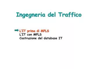
Ingegneria del Traffico con MPLS. IP convenzionale: problema. Dest. N.H. R3. R5. R1. 100 Mbit/s. R5. R6. R4. R3. Congestione !. R2. 550 Mbit/s. R7. R8. Percorso Sottoutilizzato. IT nel modello overlay. R1. 100 Mbit/s. S2. S3. S1. R3. R2. 550 Mbit/s. S4. S5.

E N D
IP convenzionale: problema Dest. N.H. ... ... R3 R5 ... ... R1 100 Mbit/s R5 R6 R4 R3 Congestione ! R2 550 Mbit/s R7 R8 Percorso Sottoutilizzato
IT nel modello overlay R1 100 Mbit/s S2 S3 S1 R3 R2 550 Mbit/s S4 S5 CVP per il traffico R1 R3 CVP per il traffico R2 R3 Collegamenti a 622 Mb/s
IT con MPLS LSP: • Possono seguireun qualsiasi percorso tra origine e destinazione • Possono essere associati a parametri di traffico e PHB • Sono regolati dai nodi di origine del LSP
Determinazione dei percorsi (espliciti: alg.on_line/off_line) • Segnalazione (RSVP-TE, CR-LDP) Estensione dei protocolli di routing IGP (Link State) per creare IT database Cosa Serve? Database IT Definizione e Caratterizzazione dei Flussi di Traffico In alternativa i percorsi espliciti possono essere selezionati in modo manuale!
Flussi e TUNNEL IT Tunnel IT: percorso lungo il qual eviene istradato un flusso di traffico LSR di uscita Flusso di Traffico LSP 1 LSR di ingresso LSP 1 + LSP 2 = Tunnel IT LSP 2
Database IT (LSR 1) Database IT (LSR 2) ... ... ... ... Collegamento 3-4 Banda fisica: 155 Mbit/s Banda max allocabile: 116,25 Mbit/s Banda residua: 26,25 Mbit/s Collegamento 3-4 Banda fisica: 155 Mbit/s Banda max allocabile: 116,25 Mbit/s Banda residua: 26,25 Mbit/s Tunnel IT 1 (50 Mbit/s) Annuncio IGP esteso Banda residua=26,25 Mbit/s LSR 2 B(1)=50 Mbit/s LSR 3 B(2)=40 Mbit/s LSR 4 LSR 1 Annuncio IGP esteso Banda residua=26,25 Mbit/s Tunnel IT 2 (40 Mbit/s) • Interfaccia STM-1 (155 Mbit/s): • Banda massima allocabile per Tunnel IT = 116,25 Mbit/s • Banda residua = 26,25 Mbit/s Database IT: esempio
IGP Esteso IT: flusso logico delle operazioni Tabella di Routing Database IT Vincoli Algoritmo Percorso “ottimo” Segnalazione (RSVP-TE/CR-LDP)
RSVP-TE B C A F E PATH D RESV RSVP-TE: RSVP + ExplicitRoute Obj ( Path) + Label Request (Resv)
RSVP-TE Tunnel IT setup LSR di ingresso LSR di uscita PATH ERO = {B, E, F} PATH ERO = {E, F} PATH ERO = {F} A F IF1 IF 0 IF1 IF 0 IF1 IF 0 B E
RSVP-TE Tunnel IT set up LSR di ingresso LSR di uscita RESV Etichetta = 89 RESV Etichetta = 57 RESV Etichetta = 3 IF1 IF 0 IF1 IF 0 IF1 IF 0 A F B E In Out In Out In Out (IF 1; 89) (IF 0; 89) (IF 1; 57) (IF 0; 57) (IF 1; Pop) Traffico FTN ILM ILM
89 57 RSVP-TE: trasferimento dati Pacchetto appartenente al flusso di traffico che utilizza il Tunnel IT B C A F E D L’LSR A è configurato per immettere nel Tunnel IT il flusso di traffico