Download

1 / 21
210 likes | 394 Vues
Thermo-mechanical Analysis of a Prototypical SiC Foam-Based Flow Channel Insert. S . Sharafat , A. Aoyama , and N. Ghoniem University of California, Los Angeles (UCLA). Brian Williams, Ultramet, Inc. Pacoima, California, 91331. FNST MEEETING AGENDA August 18-20, 2009

E N D
Thermo-mechanical Analysis of a Prototypical SiC Foam-Based Flow Channel Insert S. Sharafat, A. Aoyama, and N. Ghoniem University of California, Los Angeles (UCLA) Brian Williams, Ultramet, Inc. Pacoima, California, 91331 • FNST MEEETING AGENDA • August 18-20, 2009 • Rice Room 6764 • Boelter Hall, UCLA shahrams@ucla.edu brian.willimas.@ultramet.com
Introduction • Prototypes of FCI structures using “porous” CVD-SiC foam were fabricated • Mechanical, thermal, and electrical properties of SiC-foam core FCI materials are briefly reviewed • Thermo-mechanical performance tests and analysis of an FCI prototype were performed and will be presented
Temperature Profile for Model DEMO Case FCI Pb-Li FS GAP sFCI = 5 S/m 20 S/m 100 S/m Introduction • U.S. ITER Dual Coolant Liquid Lead (DCLL) Test Blanket Module (TBM) • Flow Channel Insert (FCI) is a key feature that makes the DCLL concept attractive for DEMO and power reactors • FCI serves 2 important functions: • Thermally insulate Pb-Li (~700 oC) from TBM structure (F82H, corr. Tmax ~ 470 oC) • Electrically insulate Pb-Li flow from steel structures.
FCI Key Requirements • Minimize Impact on Tritium Breeding • Adequate thermal insulation Kth = 2~5 W/m-K for US DCLL TBM • Adequate electrical insulation sel = 5~100 S/m for US DCLL TBM • Compatibility withPb-Li Up to 470ºC for US DCLL TBM, >700ºC for DEMO In a flowsystem with large temperature gradients • Leak Tight for Liquid Metal / disconnectedporosity Pb-Li must not “soak” into cracks or pores, must remain isolated in small pores even if cracked • Mechanical integrity Primary and secondary stresses must not endanger integrity of FCI • Retain Requirements 1 – 5 during operation Neutron irradiation in D-T phase ITER, and extended to DEMO Developing flow conditions, temperature & field gradients Repeated mechanical loading under VDE and disruption events
FCI Material Choice • Silicon Carbide (SiC) materials fulfill primary operational requirements of Flow Channel Inserts (FCIs) • A number of SiC-based FCI concepts are under development: • SiC/SiC Composites • CVI-SiC Closed Cell Syntactic Foam • CVI-SiC Open Cell Foam Core • Here we discuss Open Cell SiC-Foam Core FCI Prototypes, which were recently heat tested. • Thermo-mechanical performance tests of this FCI prototype will be discussed
FCI: CVI-SiC Core Foam Wall • CVI-SiC foam is a thermally- and electrically low conducting “porous” structure • SiC foam density can be varied to promote desired mechanical and thermal properties • (1) CVD SiC and (2) SiC/SiC composite facesheet materials are being considered for the ID and OD of the FCI to increase structural integrity and to prevent PbLi ingress • PbLi ingress through potential face sheet defects is being minimized by filling the void space within the foam with ceramic Aerogel or ceramic microspheres CVD-SiC CVI-SiC-Foam CVD-SiC Cross-sectional photographof 22% dense CVD SiC foamwith 1.8 mm thick CVDSiC face-sheets (5X) Removal of the ligament Carbon-core reduced electrical conductivity to < 0.2 S/m
CVI-SiC Core Foam FCI Properties Conductivities of SiC-Foam with CVD-SiC Face-sheet Material A: 100 ppi, 0.50” thick, 12% dense SiC foam with 0.070” thick CVD SiC faceplates Material B: 100 ppi, 0.25” thick, 20% dense SiC foam with 0.070” thick CVD SiC faceplates Material C: 100 ppi, 0.50” thick, 20% dense SiC foam with 0.035” thick CVD SiCfaceplates Material D: 100 ppi, 0.50” thick, 10% dense SiC foam infiltrated with high density SiO2 aerogel Material E: 100 ppi, 0.50” thick, 10% dense SiC foam infiltrated with low density SiO2 aerogel
FCI – Prototype Fabrications (Ultramet) • Nominal part size is 116 × 116 × 300 mm long with a 7-mm wall thickness. • Standard processing involves conversion of polyurethane foam to 99% porous carbon foam billet, which is then cut into 130 × 130 × 300 mm long pieces • The FCI ID is established by press-fitting mandrel of desired size into the foam and the ODis formed with a fly-cutter. • Finally the carbon foam is infiltrated by CVD with SiC to ~10-20 vol% • Several prototype parts have successfully been fabricated 63.5 cm FCI foam core after SiC infiltration
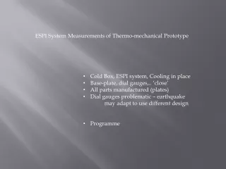
FCI – Prototype Heat Testing • Inductive Heating Tests performed on 0.15 m tall FCI segments Steady-state Temperatures ID ~ 200 oC ID ~ 600 oC • Stereo microscope inspection did not reveal any visible damage or micro-cracks.
Thermo-mechanical Analysis • Solid Model
Modeling Surrogate Foam Properties Detailed 3-D solid model, meshed open-cell SiC-foam core structure, and “surrogate material.” FEM analysis to establish “surrogate foam” properties Temperature Von Mises Estimated Surrogate SiC-Foam Material Properties Displacement
FEM Results Temperatures: ID: 596 oC OD: 464 oC • Temperature distribution is not uniform • Maximum DT occurs along midsections of FCI walls • Maximum DT ~ 137 oC
FEM Results Von Mises Stress: s > 380 MPa s > 300 MPa Deformation scale = 100 X • Stress concentrates at top/lower corners • Maximum stress is below CVD-SiC tensile strenght of ~ 300 to 400 MPa
FEM Results Strain: emax ~ 0.12 % • Strain rather than stress is a better indicator for ceramic performance • Maximum strain remains below 0.12 %
FEM Result Discussions • FCI heating tests (Dt ~ 147 oC) showed no visibly discernable sign of damage (microscopic analysis was not performed) • Conservative thermo-mechanical analysis estimates stresses to be below CVD-SiC tensile strength, even though: • FEM analysis assumes sharp interface between CVD-SiC face sheet and SiC-foam no gradual transition between CVD-SiC face sheet and SiC-foam • Mechanical properties of surrogate material for SiC foam may be underestimated (E ~ 11 GPa) • The outer 1-mm thick CVD-SiC shell carries the load
Conclusions • Several FCI prototypes structure were fabricated • The FCI wall structure consists of CVI-SiC foam core (~5 mm) between CVD-SiC face sheets (~1 mm) • Heat tests up to DT~150 oC did not result in visibly discernable damage (no microscopical analysis) • Thermo-mechanical analysis of the heat test estimates maximum stresses to be below CVD-SiC tensile strength • The heat tested performance of the FCI prototype implies that the open-cell foam core based FCI structure holds promise for TBM.
Thank you for your attention shahrams@ucla.edubrian.williams@ultramet.com
Thermo-Structural Analysis: Non-uniform DT TOP of FCI 343 oC 427 oC Back- Front - View ISO- Complete FCI Assembly MHD-Based Temperature Maps Max. Temperature Drop across FCI~ 40 oC Temperatures
FCI Material Property Requirements Effect of SiC electrical conductivity and FCI thickness on MHD pressure drop reduction factor R in poloidal flow for DEMO. Effect of the electrical and thermal conductivity of the FCI on heat losses in the DEMO blanket S. Smolentsev et al. / Fusion Engineering and Design 83 (2008) 1788–1791
SiC/SiC Un-irradiated & Irradiated Electrical Conductivity Un-irradiated Thru Thickness Irradiated Thru Thickness K.Yutai, 2008 K.Yutai, 2008
Effect of Neutron Irradiation on Electrical Conductivity of CVD SiC 1000 500 200 100 20 Temperature [ºC] Tirr ~375 meV K.Yutai, 2008 K.Yutai, 2008 (measurement done at RT) • Materials are R&H CVD SiC, n-type with nitrogen as the primary impurity. • Irradiation at lower temperature tends to result in higher carrier density x mobility. • Conduction in 1020ºC-irradiated material is governed by single defect type at all temperatures. The same defect likely dominates in other irradiated materials at relatively high temperatures.