Download
1 / 20
200 likes | 633 Vues
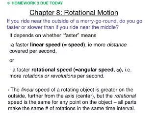
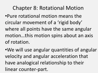
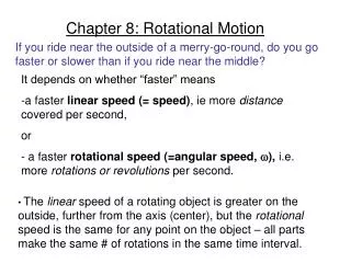
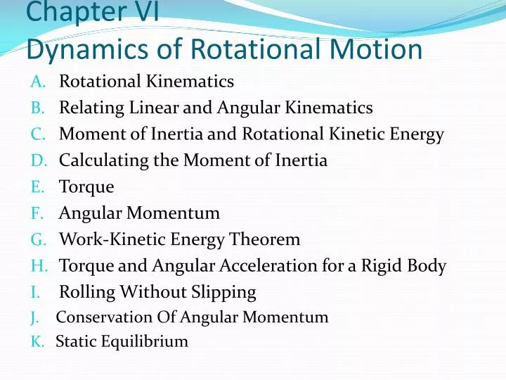
Chapter VI Dynamics of Rotational Motion. Rotational Kinematics Relating Linear and Angular Kinematics Moment of Inertia and Rotational Kinetic Energy Calculating the Moment of Inertia Torque Angular Momentum Work-Kinetic Energy Theorem Torque and Angular Acceleration for a Rigid Body

E N D
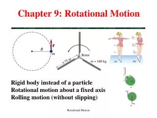
Chapter VIDynamics of Rotational Motion • Rotational Kinematics • Relating Linear and Angular Kinematics • Moment of Inertia and Rotational Kinetic Energy • Calculating the Moment of Inertia • Torque • Angular Momentum • Work-Kinetic Energy Theorem • Torque and Angular Acceleration for a Rigid Body • Rolling Without Slipping • Conservation Of Angular Momentum • Static Equilibrium
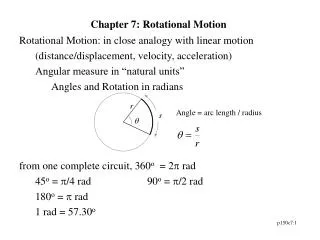
A. Rotational Kinematics One rotation, S = 2r 2 = angle = S = r = s/r
B. Relating Linear and Angular Kinematics Z & S = r ds/dt = (d/dt) r v = r v = x r dv/dt = (d/dt) r aT = r aT = x r as = v2/r = (v/r)v = v as = x v aT & v as y x
C. Moment of Inertia and Rotational Kinetic Energy A particle K1 = ½ m1 v12 = ½ m1 r122 System particle K = K1 + K2 + K3 + ... K = ½ m1 r122 + ½ m2 r222 + ... K = ½(m1 r12 + m2 r22 + ...) 2 K = ½ ( mi ri2) 2 K = ½ I 2 moment of Inertia= I = mi ri2 D. Calculating the Moment of Inertia moment of Inertia= I = mi ri2 discrete mass distribution I = r2 dm continuous mass distribution
An engineer is designing a machine part consisting of three heavy disks linked by lightweight struts (Fig.). (a) What is the moment of inertia of this body about an axis through the center of disk A, perpendicular to the plane of the diagram? (b) What is the moment of inertia about an axis through the centers of disks B and C? (c) If the body rotates about an axis through A perpendicular to the plane of the diagram, with angular speed = 4.0 rad/s, what is its kinetic energy? a) b) c)
I = r2 dm dm = dV = 2rL dr I = r2 2rL dr = 2L r3 dr I = 2L ¼ (r24 – r14) I = ½ L (r22 – r12) (r22 + r12) M = V = ( r22L - r12L) M = L (r22 – r12) I = ½ M (r22 + r12) If, r1 = 0, than I = ½ M r2 solid cylinder If, r1 = r2, than I = M r2 Thin-walled hollow cylinder r2 r2 r1 r1 r dr M L
The parallelaxis theorem There is a simple relationship between the moment of inertia Icm of a body of mass M about an axis through its center of mass and the moment of inertia Ip about any other axis parallel to the original one but displaced from it by a distance d. This relationship, called the parallelaxis theorem, states that, Ip = Icm + M d 2
The moment of inertia Icm of the slice about the axis through the centerof mass (at 0) is The moment of inertia of the slice about the axis through P is We then expand the squared terms and regroup, and obtain The second and third sums are roportional to X ern and Yern; these are zero because we have taken our origin to be the center of mass.
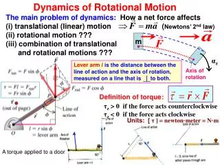
E. Torque • = r x F • = r F sin y F r r x F. Angular Momentum y p r Angular Momentum a Particle r l = r x p I = r p sin dl/dt = dr/dt x p + r x dp/dt dl/dt = v x mv + r x F dl/dt = x
Angular Momentum System Particle L = l1 + l2 + l3 + ... dL/dt = dl1/dt + dl2/dt + dl3/dt + ... dL/dt = 1 + 2 + 3 + ... dL/dt = ext
G. Work-Kinetic Energy Theorem y F W = F.S = F cos α r = F sin r dW/dt = (d/dt) Power = P = r r Work-Kinetic Energy Theorem w = K dW/dt = dK/dt dW/dt = d(½ I 2 )/dt P = ½I d(2)/dt = ½I (d2/d) (d/dt) P = ½I 2 α P = I α P = = I α x
H. Torque and Angular Acceleration for a Rigid Body For a particle F1 tan = m1 a1 tan 1 z = F1 tan r1 = m1 a1 tan r1 1 z = m1 r1αz r1 = m1 r12αz For a rigid body z = i z = mi ri2αz z = I αz (rotational analog of Newton's second law for a rigid body)
= I α T R = ½ M R2 (a/R) • T = ½ M a ................... (1) • Fy = m a mg – T = ma .............. (2) • (2) • mg – ½ M a = ma • mg = ½ M a + ma = a (½ M + m) • a = mg/(½ M + m)
I. Rolling Without Slipping IP = ICM + M R2 K = ½ IP 2 K = ½ (ICM + M R2) 2 K = ½ ICM2 + ½ M R2 2 The total kinetic energy of a rolling object is the sum of the rotational kinetic energy about the center of mass and the translational kineticenergy of the center of mass. M R Conservation of Mechanical Energy
J. CONSERVATION OF ANGULAR MOMENTUM Li = Lf Iii = Iff Decrease in the moment of inertia of the skater causes an increase inthe angular speed.
Example. An acrobatic physics professor stands at the center of a turntable, holding his arms extended horizontally with a 5.0-kg dumbbell in each hand (Fig. ). He is set rotating about a vertical axis, making one revolution in 2.0 s. Find the prof's new angular velocity ifhe pulls the dumbbells in to his stomach. His moment of inertia (without the dumbbells) is 3.0 kg . m 2 when his arms are outstretched, dropping to 2.2 kg . m 2 when his hands are at his stomach. The dumbbells are 1.0 m from the axis initially and 0.20 m from it at the end. Treat the dumbbells as particles.
We have 1z = (0.50 rev/s)(2 rad/rev) = 3.14rad/s and 2z, = (2.5 rev/s)(2rad/rev) = 15.7rad/s. Theinitial kinetic energy is The extra kinetic energy came from the work that the prof did topull his arms and the dumbbells inward.
K. Static Equilibrium Slippery wall Fx = 0 ; Fy = 0 ; = 0 Fx = 0 NA – fO = 0 ................(1) Fy = 0 NO – WL – WP = 0 .....(2) = 0 We use theconvention that the sign of the torque resulting from a force is positive if the turning tendency of the force is counterclockwise and is negative if the turning tendency is clockwise. When we take the torques about an axis through theorigin O at the bottom of the ladder, we have ½a WL + ⅓ a WP – b NA = 0 ......(3) A NA NO b ½ L ⅓ L WL WP fO O a