Download
1 / 12
120 likes | 276 Vues
MEEN 3110 – Fluid Mechanics and Applications Fall - 2010 Lecture 05. IMPACT OF A JET. Chapter Objectives. Up on completion of this lecture, the student will be able to:

E N D
MEEN 3110 – Fluid Mechanics and ApplicationsFall - 2010Lecture 05 IMPACT OF A JET
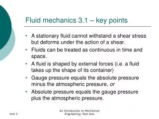
Chapter Objectives • Up on completion of this lecture, the student will be able to: • Calculate the force produced by a flow of water acting on a vane, and compare it with the experimental values of rate of change of momentum in the system as well as the theoretical ones.
5.1 Theory Consider a vane symmetrical about the x-axis as shown in Figure 2.0. A jet of fluid flowing at the rate of (m dot) kg/s along the x-axis with the velocity u0 m/s strikes the vane and is deflected by it through angle β,so that the fluid leaves the vane with the velocity u0 m/s inclined at an angle β to the x-axis.
5.2 Procedure The apparatus is first leveled and the lever set to the balanced position (as indicated by the tally) with the jockey weight at its zero position. Water is admitted through the bench supply valve. The rate of flow is then increased to the maximum and the position of the jockey weight which restores the lever to the balanced position is noted, while the discharge is weighed in the weighing tank. A series of about eight readings with roughly equally spaced positions of the jockey weight, are then taken by decreasing the flow rate from the bench. (Adjust weight of water collected to ensure discharge over 60 seconds). The experiment may then be repeated using the hemispherical cup, conical plate and angled plate in turn. The diameter of the nozzle, the height of the vane above the tip of the nozzle when the lever is balanced, the distance between the centre of the vane and the pivot of the lever and the jockey weight should be noted.