Download
1 / 47
530 likes | 933 Vues
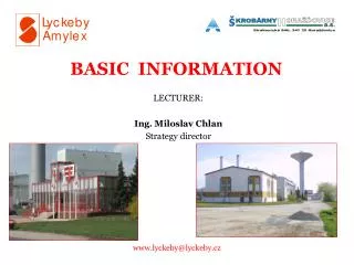
Basic Information. O/C E/F Relay & Time Coordination Basic Information. General Circuit Diagram. 200/1 Amp. P1. P2. 150 Amp. 150 Amp. 150 Amp. C71. S2. R Ph O/C (51R). 0.75 Amp. S1. C11. E/F (51N). C31. 0.75 Amp. S1. 0.0 Amp. B Ph O/C (51B). S1. C51. 0.75 Amp. A11. 1S1R.

E N D
O/C E/F Relay & Time Coordination Basic Information O/C E/F Relay & Time CoordinationBasic Information
O/C E/F Relay & Time Coordination General Circuit Diagram 200/1 Amp P1 P2 150 Amp 150 Amp 150 Amp C71 S2 R Ph O/C (51R) 0.75 Amp S1 C11 E/F (51N) C31 0.75 Amp S1 0.0 Amp B Ph O/C (51B) S1 C51 0.75 Amp
O/C E/F Relay & Time Coordination A11 1S1R 1S2R R Ph CT Yard MB Wiring 1S3R A31 Core-3 Core-2 Core-1 1S1Y 1S2Y 1S3Y A51 1S1B 1S2B A71 1S3B 2S1R C11 2S2R Y Ph CT 2S3R Core-3 Core-2 Core-1 2S1Y C31 2S2Y 2S3Y C51 2S1B 2S2B C71 2S3B D71 3S1R B Ph CT 3S2R Core-3 Core-2 Core-1 3S3R D11 3S1Y 3S2Y 3S3Y D31 3S1B 3S2B 3S3B D51
O/C E/F Relay & Time Coordination A11 1S1R 1S2R R Ph CT Yard MB Wiring 1S3R A31 Core-3 Core-2 Core-1 1S1Y 1S2Y 1S3Y A51 1S1B 1S2B A71 1S3B 2S1R C11 2S2R Y Ph CT 2S3R Core-3 Core-2 Core-1 2S1Y C31 2S2Y 2S3Y C51 2S1B 2S2B C71 2S3B D71 3S1R B Ph CT 3S2R Core-3 Core-2 Core-1 3S3R D11 3S1Y 3S2Y 3S3Y D31 3S1B 3S2B 3S3B D51
O/C E/F Relay & Time Coordination Terminal Diagram of MiComP141
O/C E/F Relay & Time Coordination Single Line to Ground Fault 200/1 Amp P1 P2 1500 Amp C71 S2 R Ph O/C (51R) 7.5 Amp S1 C11 E/F (51N) C31 S1 7.5 Amp B Ph O/C (51B) S1 C51
O/C E/F Relay & Time Coordination Electromagnetic Induction relays 50% 75% 100% 125% 150% 200% Φ 1 Φ 2
O/C E/F Relay & Time Coordination Relay Operation Time - 1 E/F PSM 30% i.e. 0.3 Amp E/F Relay Current 7.5 Amp E/F Relay Current is 7.5/0.3 = 25 Times its operating current From Graph for 25 Times relay operating current for TMS = 0.15 relay time of operation would be @ 0.35 Sec O/C PSM 100% O/C Relay Current 7.5 Amp It is 7.5 times relay operating current From graph for 7.5 Times relay operating current and for TMS = 0.1 time of operation for the relay would be 0.35 Sec ( Zoom out Graph)
O/C E/F Relay & Time Coordination Relay Operation Time - 2 Actually our problem is to decide relay settings and not relay time of operations as shown previously Hence Unknowns are Relay PSM Relay TMS Whereas known facts are Relay placement and purpose of use Relay current during fault ( i.e. CT secondary current during fault. ) Relay desired time of operation. General Steps 1) Decide PSM 2) Find out fault current 3) Find out multiple of relay set current as per decided PSM in step-1 4) Find out time of operation for above multiple of current and TMS=1 using relay characteristic curve 5) Decide relay time of operation as per protection needs 6) Find out TMS = Required Time of operation /Time of operation with TMS =1
O/C E/F Relay & Time Coordination Basic Information – Selection of PSM • E/F PSM generally selected as 30% ( Other than 30% settings may also be selected but about this discussed somewhere else in the presentation) • For O/C PSM is selection depends upon place and purpose of use for example – • Transformer O/C protection • Transformer HV or LV side O/C relay PSM settings should be in commensuration with transformer full load current and respective CT ratio such that PSM = T/F Full load current / CT ratio ( Generally expressed in %) • For example for a 25 MVA transformer HV side full load current is 109 A if HV CT ratio is 200/1 Amp then PSM =109/200 ≈ 55% ( exact value 54.5%) • For old type numerical relay it was not possible to go as near as possible to value calculated from above formula due to large steps available • Under such condition it is decision as per local condition to select higher or lower nearest PSM • In above example it is customary to select 50%, however due to this selection there is apparent loss of about 10% capacity of the T/F • It is also possible to select 75% but load on transformer is to be monitored carefully ( and manually ) • For 220-132 kV feeder • Here generally it is customary to select relay PSM as per- • Line conductor allowable loading limit • CT primary normal current • Substations capacity/normal load feed by the line • Considering above facts it is very common to select 100% PSM for 132kV lines with CT ratio 400/1 Amp • For 220kV lines with CT ratio 800/1 amp and conductor 0.4 ACSR or 0.525 AAAC it is 100% • For 33-11kV feeder • As per local feeder condition, load pattern and needs ranging between 50% to 100%
O/C E/F Relay & Time Coordination Relay Operation Time - 3 Desired time of operation will depend upon • Equipment being protected • Time discrimination from down stream protection (150 ms – 250 ms) • Time of operation of main protection etc. • For transformer LV side protection it is common to adopt 250 ms as operating time. • This is so as to have 150 ms time discrimination from 100 ms relay time of operation for lower (feeder) protection. • When relays are used as backup protection of 132kV lines it’s time of operation shall be equal to Z-2 time of operation (300 – 350 ms). • Once these two things decided there remains only mathematical part
O/C E/F Relay & Time Coordination Worked out Example 132 kV 33 kV 400/1 A 25 MVA 400/1 A 33kV Bus fault level 1Ph 170 MVA , 3Ph 210 MVA Relay current during fault 1Ph 7.43 Amp, 3 Ph 9.18 Amp Relay PSM E/F 30%,O/C 100 % Multiple of relay current E/F 25, O/C 9. Time of operation with TMS = 1 E/F 2.2 s, O/C 3.0 Sec Desired time of operation E/F 250 ms, O/C 250 ms TMS E/F 0.114, O/C 0.083 Roundup to E/F 0.125, O/C 0.1
O/C E/F Relay & Time Coordination More Information O/C E/F Relay & Time CoordinationMore Information
O/C E/F Relay & Time Coordination Introduction • Fuse wire is simplest protection • Fusing ampere of copper wire of diameter ‘d’ expressed in ‘Cm’ is given by the formula A = 2530*d3/2 • Time taken by fuse to blow off depends up on fusing amperes
O/C E/F Relay & Time Coordination Introduction • For a wire of length L carrying current I and diameter d heat produced is • H = I2R • H = I2σ (L/A) • H = I2σ ( L/(πd2/4)) • Heat dissipated = K’ (πd)L ( i.e. proportional to surface area where K’ is constant of proportionality) • Temperature will be steady state if heat generated is equal heat dissipated or • I2σ ( L/(πd2/4)) = K’ (πd)L • I2σ ( 1/(d2/4)) = K’ d • I2 =K’’ d3 • I = K d 3/2 • And by experiments for normal ambient temperature value of K for copper is determined as 2530 for d expressed in Cm. More
O/C E/F Relay & Time Coordination Protection of transformer by a fuse
O/C E/F Relay & Time Coordination Simplest Protection – Fuse • These characteristic graphs are generally double log graph • This is due to including from very small to very large values on both axis
O/C E/F Relay & Time Coordination Simplest Protection - Fuse • Log scale graph are use full tool where range of values varies very widely • This variation in range is generally 10,000 times • It does not affect overall accuracy of selecting proper value manually
O/C E/F Relay & Time Coordination • General mathematical formula for time characteristic of the relay as per IEC Standards K Time Of Operation = --------------------- ( ( Is/Ib)α- 1 )
O/C E/F Relay & Time Coordination • General mathematical formula for time characteristic of the relay shown on previous slide, with parameter values for different curves are shown here
O/C E/F Relay & Time Coordination Use of log scale-1
O/C E/F Relay & Time Coordination Use of Log Scale-2
O/C E/F Relay & Time Coordination Use of Log Scale-3
O/C E/F Relay & Time Coordination Use of Log Scale-4
O/C E/F Relay & Time Coordination Transformer – Protection – Damage Curve • Damages to the equipment due to fault current flowing through it are mainly due to heating effect of the current ( I2Rt) • Hence fuse time characteristic initially suited very well to the equipments in the power system • This figure shows protection of transformer with the help of relay and breaker • This also indicates how inverse characteristic of O/C Relay is suitable to protection of power system equipments • ( More about Transformer Damage Curves) • ( More about this figure )
O/C E/F Relay & Time Coordination Transformer – Protection – Damage Curve • Transformer damage curve as per IEEE 57.109 for class – III transformers ( 5 MVA to 30 MVA )
O/C E/F Relay & Time Coordination Protection of Transformer by O/C Relay Long Time Inverse Trafo Damage Curve Extremely Inverse Normal Inverse
O/C E/F Relay & Time Coordination End of More Information After understanding basics of relay characteristic curves and its selection according to protection needs we will turn to allied information about O/C E//F relaying This allied information will prove helpful in overall understanding about development of protective relays and its use in power system
O/C E/F Relay & Time Coordination Basic Information O/C E/F Relay & Time CoordinationAllied Information
O/C E/F Relay & Time Coordination Disadvantages of fuses • Though simple less accurate ( If Rewirable) • Because of previous heating effect • Ambient Temperature • In consistencies in material • Limitations for breaking capacities hence suitable for LV and to some extent MV • HRC Fuses • More accurate • Higher rupturing capacities • Requires time for replacement • Suitable for LV and to some extent MV
O/C E/F Relay & Time Coordination Early Development of Protective Schemes • This simple device (Fuse) played a very vital role during early development of power systems • As the complexity of power system increased other technique get introduced like breaker, relay DC battery etc. (How?)
O/C E/F Relay & Time Coordination Early development of power system • History of power system protection dates back nearly to the start of development of power system it self • In real sense power system started growing due to invention of incandescent lamp by Edison during 1880 • Edison was promoter of DC power system ( Why ? ) • General Electric founded by him was main supplier of electricity in Newyork. • Washington first introduced AC system with the advancement in transformer during 1887 • During 1890 charls introduced symmetrical component analysis which helped in analyzing 3 ph. Power system and there by possible to design larger machines and power systems. • Modern day power system came into existence from 1890 • One of the patent of fuse is in the name of Edison • Development of relays breakers and instrument transformers took place during 1890 to 1920 and modern day protection system came into existence. • And during last century development of power system continuous to be there however main principles of power system protection are 3S and 1R remained same. • Development of relays breakers and instrument transformers took place during 1890 to 1920 and modern day protection system came into existence. • And during last century development of power system continuous to be there however main principles of power system protection are 3S and 1R remained same.
O/C E/F Relay & Time Coordination General Requirements of Protective Scheme • For any protective device following Functional Characteristic are important. • Sensitive • Selectivity • Speed • Reliability • ( Note:- 3 S & 1 R) • As a improvement over simple fuses (in above areas) other protective devices get developed with the advancement of power system
O/C E/F Relay & Time Coordination 3S & 1R • Sensitivity is that property of protection system which enables it to distinguish between fault and no fault condition very correctly. • As if we say that some animals are more sensitive than humans to natural disasters like earthquake. • Where as selectivity is that property of the power system which enables it to isolate only the faulty part from healthy part. • In this sense differential protection is most selective protection • Once the fault detected by SENSITIVE system and area to be disconnected detected by SELECTIVE system then there comes the SPEED. • This faulty section should be get cleared as early as possible. • For EHV system Faults are once in blue moon. Hence this all above said things should happen RELIABELY even after 5-10 years from design and commissioning of the protection system.
O/C E/F Relay & Time Coordination Changing Trend In Protective Relaying • Protection relay is a tool for protection engineer • During last 30 years relay operating principles changed very drastically • Electromagnetic Relays • Static Relays • Digital Relays • Numerical Relays • Though it is not required to design a relay or repair a relay at site it is customary to have some working knowledge of these relays for better understanding and use of it
O/C E/F Relay & Time Coordination Electromagnetic Induction relays
O/C E/F Relay & Time Coordination Static Relays
O/C E/F Relay & Time Coordination Digital Relay
O/C E/F Relay & Time Coordination Numerical Relay Functions Available in Numerical O/C Relay
O/C E/F Relay & Time Coordination Introduction A B C R3 R2 R1 500 ms 350 ms 110 ms • Consider a representative part of a power system as shown above. • It is being protected by over current relay • Typical expected time of operation for over current relays are as shown • In next couple of hour we will see • What is mean by relay characteristics curve • How relay characteristic curve suites our protection needs • How it helps us in deciding relay time of operation • Workout relay settings so that they shall operate at expected time • Methodology being adopted for selective tripping by over current relay including directional relay
O/C E/F Relay & Time Coordination Introduction S A B C R3 R2 R1 40 sec. 25 sec. 10 sec. S A B C R3 R2 R1 180 ms 220 ms 200 ms S R3 R2 R1 500 ms 350 ms 110 ms
O/C E/F Relay & Time Coordination Study of Time Co-ordination and its role in design of protection scheme. • Over Current and Earth Fault Protection is used for • Protecting a equipment • Selective tripping of faulty section of the power system • Backing up the main protection
O/C E/F Relay & Time Coordination Role of Over Current Relay in Protecting the Equipment • It is obvious that over current protective system should act and interrupt the fault current before to damage of equipment due to fault current through it. • Power system equipments include Line, Isolator, CT, Breaker, Transformer • Obviously Transformer is most costliest and delicate (for fault currents) equipment first we will consider its damage curve and decide parameters of protection system so that it should act fast enough to protect the transformer • This can be ascertained with the help of Damage Curve of the transformer and time-current curve of the protective system
O/C E/F Relay & Time Coordination Role of Over Current Protection in Selective Tripping • It is obvious that only that part of the power system should get disconnected where the fault exists • Hence proper time co-ordination should be there so as to let the down stream protection should act fast enough and up-stream protection should give sufficient time for down stream protection to act • Otherwise un-necessary larger area get affected
O/C E/F Relay & Time Coordination Backup Protection • When ever main protection fails to separate the faulty section backup protection take up this role • As such there is inherent time delay in operation of backup protection • This backup protection can be employed in main protection itself as additional function, but invariably it is employed as a separate relay to ensure it’s operation even if failure of quantities/links which are common to both functions such as- • DC Source • PT supply • Relay hardware • Main CTs
O/C E/F Relay & Time Coordination Back up protection • EHV line faults are of sever nature from power system security and stability point of view. Hence must be cleared instantaneously • For this purpose distance relays which operates instantaneously (Z1) are employed for protection of EHV lines • For protection of EHV transformers differential and REF relays are employed which are also instantaneous
O/C E/F Relay & Time Coordination Backup Relay Time Coordination X Y M E Z A C F