Download
1 / 30
310 likes | 467 Vues
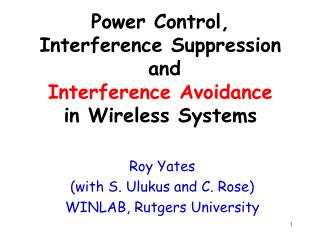
Digital Receiver with Interference Suppression for Microwave Radiometry. NASA Instrument Incubator Program Year 3 Interim Review Joel T. Johnson, Steven W. Ellingson*, and Grant A. Hampson. Outline. Slides 1-8: Administrative issues Slides 9-20: Progress in experiments

E N D
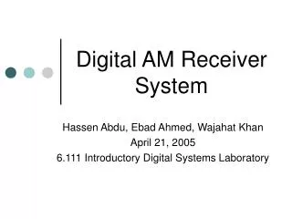
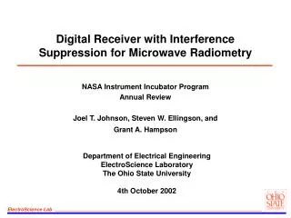
Digital Receiver with Interference Suppression for Microwave Radiometry NASA Instrument Incubator Program Year 3 Interim Review Joel T. Johnson, Steven W. Ellingson*, and Grant A. Hampson
Outline • Slides 1-8: Administrative issues • Slides 9-20: Progress in experiments • Slides 21-30: Algorithm studies with LISA/IIP data
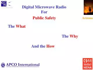
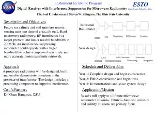
Traditional Radiometer Antenna LNA Downconv. ADC Corr/Integrate (optional) New design LNA ADC Corr/Integrate Antenna Downconv. RFI Processor Digital Receiver With Interference Suppression for Microwave Radiometry PI: Joel T. Johnson, The Ohio State University Objective • Future sea salinity and soil moisture remote sensing missions depend critically on L-Band microwave radiometry. RF interference is a major problem and limits useable bandwidth to 20 MHz. An interference suppressing radiometer could operate with a larger bandwidth to achieve improved sensitivity and more accurate moisture/salinity retrievals. A new receiver architecture will be developed that will significantly reduce radio frequency interference (RFI) in L-band radiometers. Approach Key Milestones • Complete Instrument Design – 08/02 • Complete Breadboard Fabrication – 11/03 • Initial Field Tests at OSU – 10-11/03 • Complete Large Scale Tests – 11/04 • Complete Space Applications Study – 11/04 • Final Report – 11/04 A prototype radiometer will be designed, built, and used to demonstrate operation in the presence of interference. The design includes a processing component to suppress interference. Ground based tests will be conducted to demonstrate RFI suppression. CoIs: Grant Hampson, Ohio State Steven W. Ellingson, Virginia Polytechnic TRLin =3
Project Schedule • Project “year 1” was 9 months, 3/11/02-11/30/02
Progress in Year Three • Current Milestone: “Progress of larger scale observations” • Revised front/end downconverter • “Max hold” implemented to assist in RFI identification; APB “scale-up” counter also designed • Continuing to address problems with water pool observations • Sky observations begun to provide alternate demonstration • Current Milestone: “Progress of studies of space deployment and advanced algorithms” • Study of APB algorithm using LISA data • Software simulator under development for system study • Per bin/CW interference suppression algorithms under development • Single FPGA prototype nearing completion; makes testing improved algorithms possible • Current TRL Status: In transition from TRL 3 to TRL 4
Budget/Personnel • Years 1-3 budget: 832.8K + 21K equipment • Remaining as of 4/30: ~215K + 0K equipment for 7 months • End date extension? • Current Personnel: • Co-Pis: J. T. Johnson, S. W. Ellingson • Lead Designer: G. A. Hampson (left OSU 4/30) • System Engineer: R. Krishnamarachi • Technician: Jim Moncrief • Graduate Student: Noppasin Niamsuwan • Undergrad: Scott Orlove • Document Server: http://esl.eng.ohio-state.edu/~swe/iip/docserv.html
Plans for 5/1/04-11/30/04 • Top priority is generating convincing system demonstration by solving water pool observation problems and/or use of sky measurements • Continue algorithmic assessment using LISA and IIP data; goal is an end-to-end software demonstrator with “capture” data as input • Initiate receiver architectural trade-off studies and hardware survey • Currently involved with C. Ruf (U. Mich) and J. Piepmeier (GSFC) in possible proposal for a digital receiver in the “Hydros” instrument • Project supported by NPOESS IPO on use of system at C-band is currently in progress; first flight at C-band expected July 2004 • Some interest in L-band flights of this backend for the Aquarius/Hydros missions; assess RFI environment for mission planning
Publications Recent/Upcoming Presentations: • G. A. Hampson, S. W. Ellingson, and J. T. Johnson, “Design and Demonstration of an interference suppressing microwave radiometer,” IEEE Aerospace Conference, 2004. • J. T. Johnson, A. J. Gasiewski, G. A. Hampson,S. W. Ellingson, R. Krishnamarachi, and M. Klein,``Airborne radio frequency interference studies at C-band using a digital receiver,'‘ submitted to IEEE Geoscience and Remote Sensing Symposium, 2004. • J. T. Johnson, G. A. Hampson, and S. W. Ellingson, ``Design and demonstration of an interference suppressing microwave radiometer,'‘ submitted to IEEE Geoscience and Remote Sensing Symposium, 2004. • N. Niamsuwan, J. T. Johnson, and S. W. Ellingson, “Examination of a simple pulse blanking technique for RFI mitigation,” submitted to RFI 2004: Workshop for mitigation of RFI in radio astronomy.
System Block Diagram Low-noise front end Analog Downconverter Digital Downconverter Antenna ADC Asynchronous Pulse Blanker 1024 point FFT Frequency domain blanker (not yet implemented) Integration Data Recording/ Control
Digital Back-End • System design includes digital IF downconverter (DIF), asynchronous pulse blanker (APB), FFT stage, and SDP operations • Microcontroller interface via ethernet for setting on-chip parameters • Altera "Stratix" FPGA’s: apprx 10000 LE, $260 • A final prototype has been designed to combine processor components into one Stratix FPGA: apprx 30000 LE, $950 • “Max hold” operation added to SDP; blanking counter added to APB for calibration correction – testing in progress ADC Analog Devices 9410 DIF APB FFT SDP ADC 100 MSPS I/Q 200 MSPS
ADC DIF/ APB FFT SDP Capture ADC Current Digital Back-End Implementation • Modular form used for processor boards: note microcontrollers • EEPROM's on each card for autoprogramming of FPGA's on power-up
Modified Antenna/Front End Unit • Front end Tsys approx. 200K neglecting antenna Approx 40’ RG8 ~5 dB loss Custom, high performance isolators added Previous 1250-1500 MHz filter replaced with 1325-1425 MHz Mechanical switch limits switching speed and ultimate duty cycle when Dicke switching; not clear that this is a real problem at present
Revised Dual Channel Downconverter • One channel is ~1325-1375 MHz, other is ~1375-1425 MHz • Downconverter, digital receiver, computer, and thermal control systems in rack inside lab • All amplifiers replaced with higher power models; added isolators to reduce channel coupling; replaced previous wider filter
Height (m) Experiments at OSU • Experiments designed to demonstrate radiometric accuracy in the presence of interference • Observations of a large water tank; external cal sources are ambient absorbers and a sky reflector • Highly accurate ground-based radiometry is tough due to contributions from objects not under view, including reflections • Keep cal targets exactly the same size as pool to reduce these effects; observations of pool as ambient temp varies also • Initial tests in existing RFI; artificial RFI to be added as tests progress
Absorbers: Assume Tb=Tphys Reflectors: Assume Tb=Tref~Tsky? Water: Tb~Twat+QTref Pool and Cal Targets
Example Calibrated Brightnesses: 4/20/04 • Data still show strong spectral variations that are unreasonable for water pool; clearly some kind of RFI or calibration problem • Patterns in frequency are not repeatable from one measurement to the next
Relative Power Variations: Pool Observation Blanker Off: H pol Blanker On: H pol 240 secs Noise Generator Terminator
Sky Observations • An alternate experiment was initiated using observations of the sky; a 3 m reflector with an L-band feed plus LNA was available • Sky observations at declination angle 17 degrees • Expect to see cold sky plus astronomical sources; minor atmospheric influence • Potential for using cold sky plus moon in a calibration • Initial results use software FFT’s and integration; low duty cycle as a result • 24 hour observations of astronomical sources
Sky Observation Results: Blanker on • Software FFT’s allow very high spectral resolution (~4 kHz); sufficient to observe Doppler shift of neutral Hydrogen line Hydrogen line emission around 1420 MHz; “S-curve” is due to Doppler shift associated with galactic region observed Elapsed Time (Hr) Moon
Blanker off Blanker on Sky Observations: Relative Power • Measurements were taken on successive evenings – not contiguous • Simple front end here may be source of some of these variations; plan to replace with front end from pool observations • Central variations associated with moon passing through beam • Use this measurement to assess hardware versus RFI versus pool environment variations dB
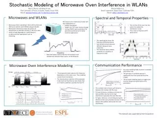
LISA: L-Band Interference Surveyor/Analyzer S.W. Ellingson, J.T. Johnson, and G.A. Hampson, The Ohio State University Nadir-looking cavity-backed spiral antenna w/ custom LNA & calibration electronics in tail radome NASA’s P-3 Orion Research Aircraft Maiden LISA Flight: January 2, 2003 from Wallops Island, VA RF distribution, antenna unit control & coherent sampling subsystem Spectrum analyzer, electronics rack & control console mounted in cabin Examples of RFI observed at 20,000 feet LISA co-observes with existing passive microwave sensors to identify sources of damaging radio frequency interference (RFI) • 1200-1700 MHz using broadbeam spiral antenna • Spectrum analyzer for full-bandwidth monitoring of power spectral density • 14 MHz (8+8 bit @ 20 MSPS) coherent sampling capability for waveform capture and analysis • Flexible script command language for system control & experiment automation
LISA Wakasa Bay Campaign • LISA was deployed in the AMSR-E "Wakasa Bay" cal-val campaign; thanks to E. Kim and R. Austin (Co. State) for operations • Antenna in P-3 radome: high loss decreased sensitivity • On board, permanent RFI for frequencies <~1320 MHz • Problems with receiver compression in many cases; high loss helped! • Some software/control issues resulted in a few cases of data loss
LISA Results Summary • Campaign produced 8 GB of data: basic unit is an 819.2 microsecond “capture”; requires 1 second, repeated 5 times successively • Numerous ARSR systems observed both in Japan and US; can correlate data versus ARSR position to examine range effects • Other radars also observed: chirped, varying pulse widths, multiple frequencies, etc. • Japanese data show some wideband channels, also a satellite downlink (1698 MHz); tests with these will challenge simple suppression algorithms • Detailed examination of 1411-1425 MHz channel shows numerous triggers, but signal properties are difficult to classify • Using cross-US flight data at present to evaluate APB performance; software implementation of APB algorithm
NBLANK NWAIT Threshold NSEP APB algorithm • APB updates mean/variance of incoming time domain signal; a sample > b standard deviations above the mean triggers blanker • Current hardware APB algorithm operates on ¼ of incoming data due to processing requirements; simulate effects in software • Current hardware APB algorithm has only a 4K FIFO; NWAIT parameter limited by this
NO BLANK ALL BLANK PARTIAL BLANK APB Study Results: Partially Blanked Frames • Using NBLANK=2048 (102.4 msec), b2=90 Split 16K sample into 32 x 512 point frames Frames separated into “NO BLANK”, “ALL BLANK”, and “PARTIAL BLANK” Spectra over 32 frames power averaged either including or not including partially blanked frames Results fairly insensitive to inclusion of partially blanked frames
APB Result: A Partially Blanked Frame • Partially blanked frames do distort spectrum – see example below • At present, no scaling is implemented, so contribution of greatly blanked frames to average is small • With scaling, spectral distortion could be an issue • Computing an average scale factor is a way around this; greatly blanked frames remain reduced – approach of “APB Counter”
APB Study Results: Problematic Cases • We can perform a chi-square test on the data after blanking as a test; the left LISA example shows a successful case, while for the right case, chi-square values were never satisfactory • Moral of the story: difficult to recover noise with too many pulses
Spectral Domain RFI Processing • A per-bin time domain blanking strategy similar to the APB can be implemented in the SDP component; higher SNR for better blanking • Cross frequency algorithms: at high speed, data will not be calibrated; can still search for regions of rapid change across frequency • For true CW interferers, rapid temporal processing may not be necessary; software scheme to throw out corrupted bins would be fine • Similar to algorithms used for analog sub-band radiometers (e.g. PSR C-band system) • Digital receiver gives capability of obtaining a large number of bins (here 1024) as opposed to only a few with analog sub-channels
Bin Blanking Example • Even with APB-on, some pulsed RFI remains after FFT; here the simple APB algorithm is applied to each bin Algorithm removes some remaining RFI in each bin; simple enough to consider implementing in hardware
Software Bin Blanking Algorithm • An algorithm based on the chi-square test has also been implemented; somewhat complex for hardware implementation but ok for software Data is from IIP water pool observations Bin results are sorted by amplitude; highest amplitude results are gradually excluded until a minimum chi-square value is achieved Similar to PSR multi- channel RFI suppression algorithm