Download
1 / 50
520 likes | 739 Vues
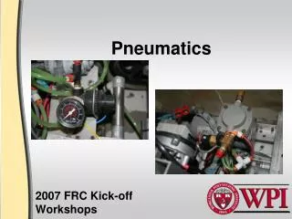
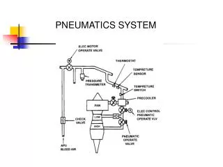
FRC Pneumatics. Nate Laverdure FRC Team 122. What is this presentation?. Goals: Teach you the words transducer , damper , and venturi Attempt to: Show that pneumatics have great advantages – if used correctly! Provide a workable understanding of FRC pneumatics My personal goal:

E N D
FRC Pneumatics Nate Laverdure FRC Team 122
What is this presentation? Goals: • Teach you the words transducer, damper, and venturi • Attempt to: • Show that pneumatics have great advantages – if used correctly! • Provide a workable understanding of FRC pneumatics My personal goal: inspire you to build your own pneumatic system!
Alternative configurations Three major categories: • On-board compression • Off-board compression • Serious off-board compression
PS CMP TANK HP TANK MP LP
PS CMP TANK HP Off-board TANK MP LP
Off-board compression Why? • Less weight (about 5 lb) • Less power draw during the match
Off-board compression Why not? • No pressure regeneration during the match • No way to replace pressure lost to leaks • Adds an additional pre-match check
Off-board compression limitations Off-board compressor must be: • Powered by robot Power must come from Spike Relay on robot • Controlled by robot Via pressure switch Digital Sidecar cRIO • Protected by relief valve • Ventable Requires additional vent valve
PS CMP TANK HP Off-board TANK MP LP
PS CMP TANK HP Seriously off-board TANK MP LP
Serious off-board compression All the limitations of standard off-board compression, PLUS: • On-board storage is limited to only 60 psig
Building a pneumatic system General guidelines: • Read, know, and understand all the FRC pneumatics rules • Be able to explain your system to the inspectors
Building a pneumatic system General guidelines: • Read, know, and understand all the FRC pneumatics rules • Be able to explain your system to the inspectors Here’s a $6,000 hint: Refer to a printed flow diagram during inspection!
Building a pneumatic system Tips for tube fittings: • Use plastic push-to-connect fittings where possible (Less weight compared to brass fittings)
Building a pneumatic system Tips for tube fittings: • To connect: push tube in until firmly seated • To remove: press rim down, then pull tube out • Tubes cut at an angle will leak
Building a pneumatic system Tips for teflon tape: • Use 4 to 6 wraps of tape • Don’t use tape more than once • Wrap tape in the right direction • Don’t allow loose pieces of tape to get into the tubing
Building a pneumatic system Tips for brass fittings: • Brass is very soft • Do not over-torque • Do not use adjustable wrenches • Use box-end wrenches where possible
Caring for your pneumatics Problems maintaining pressure: Chronic leak Acute catastrophic pressure loss
Caring for your pneumatics Problems maintaining pressure: Chronic leak Acute catastrophic pressure loss Catastrophic pressure loss may be caused by: • Tube disconnection or breakage • Component failure
Caring for your pneumatics Tips for avoiding leaks: • Use as few fittings as possible • Perform leak test as each component is added • Use leak test fluid
Leak test fluid Recipe: • Add 2 tbsp dish soap to empty spray bottle • Fill spray bottle with water Directions: • Shake well • Cover all exposed electrical parts! • Spray directly on pressurized pneumatics
Caring for your pneumatics Protect your cylinders— • Thin wall tube can be crushed by side impacts • Internal seals will not handle side loads • Not repairable!
Design sequence • Find the required stroke length • Find the force & set the operating pressure • Guess how many times you will actuate the cylinder during a typical match • Find the required storage capacity
Determining the actuation force P1 P2 A
Determining the actuation force F1= P1A F2= P2A
Determining the actuation force F = F1 – F2= A(P1 – P2)
Determining the actuation force Warning: simplification! Because of piston rod, A1≠ A2 F = F1 – F2= A(P1 – P2)
Determining the actuation force P 0 F = F1 – F2= A(P1 – P2) F = PA
Example • Find the required stroke length • Find the force & set the operating pressure • Guess how many times you will actuate the cylinder during a typical match • Find the required storage capacity
Example Cylinder Stroke length L = 3 in L
Example • Find the required stroke length • Find the force & set the operating pressure • Guess how many times you will actuate the cylinder during a typical match • Find the required storage capacity
Example Cylinder Stroke length L = 3 in Diameter d = 1 in Area A = (d2)(π/4) = .785 in2 d L P
Example Cylinder Stroke length L = 3 in Diameter d = 1 in Area A = (d2)(π/4) = .785 in2 Pressure Puse = 60 psig = 60 lbf/in2 d L P
Example Cylinder Stroke length L = 3 in Diameter d = 1 in Area A = (d2)(π/4) = .785 in2 Pressure Puse = 60 psig = 60 lbf/in2 Force F = (Puse)(A) = 47 lbf d L P
Example • Find the required stroke length • Find the force & set the operating pressure • Guess how many times you will actuate the cylinder during a typical match • Find the required storage capacity
Example Cylinder # Actuations Nactuations = 10 + 10 = 20
Example Cylinder # Actuations Nactuations = 10 + 10 = 20 Warning: Remember to count both the forward and reverse strokes!
Example Cylinder # Actuations Nactuations = 10 + 10 = 20 Gas use = ~(Nactuations)(Puse)(Vcyl) = (20)(60 psig)(2.36 in3) = 2832 in*lbf
Example Cylinder # Actuations Nactuations = 10 + 10 = 20 Gas use = ~(Nactuations)(Puse)(Vcyl) = (20)(60 psig)(2.36 in3) = 2832 in*lbf This is in units of energy!
Example • Find the required stroke length • Find the force & set the operating pressure • Guess how many times you will actuate the cylinder during a typical match • Find the required storage capacity
Example Storage Volume Vtank = (L)(A) = 16 in3 Pressure Pstore = 120 psig # Tanks Ntanks = 2
Example Storage Volume Vtank = (L)(A) = 16 in3 Pressure Pstore = 120 psig # Tanks Ntanks = 2 Gas storage = ~(Ntanks)(Pstore)(Vtank) = (2)(120 psig)(16 in3) = 3840 in*lbf
Is the example design OK? Safety factor η = Gas storage 3840 in*lbf Gas use 2832 in*lbf = = 1.36 =
Is the example design OK? Safety factor η = Gas storage 3840 in*lbf Gas use 2832 in*lbf = = 1.36 = Result: The design is marginal. Add another tank, then test to make sure it works!
Gotchas Inspection checklist: • Relief valve is set at 125 psig • Off-board compressor must be controlled by cRIO • Vent valve must release all system pressure
Gotchas Inspection checklist: • Relief valve is set at 125 psig • Off-board compressor must be controlled by cRIO • Vent valve must release all system pressure Mitigations: • The KOP relief valve is not pre-calibrated! Set the relief valve per instructions.
Gotchas Inspection checklist: • Relief valve is set at 125 psig • Off-board compressor must be controlled by cRIO • Vent valve must release all system pressure Mitigations: • Build an off-board compression rig, complete with: • Compressor • Relief valve • Vent valve • Pressure gauge • Do not use shop air!
Gotchas Inspection checklist: • Relief valve is set at 125 psig • Off-board compressor must be controlled by cRIO • Vent valve must release all system pressure Mitigations: • Test all configurations • Can be caused by: • Solenoids with closed center positions • Systems that switch between pressures • Systems that stop cylinders partway through their stroke
FRC Pneumatics Nate Laverdure FRC Team 122