Download
1 / 34
340 likes | 485 Vues
Probing magnetism and ferroelectricity with x-ray microdiffraction. Paul Evans, University of Wisconsin evans@engr.wisc.edu. October 9, 2002. Outline. Magnetic and Polarization Domains in Solids Hard X-ray Microdiffraction

E N D
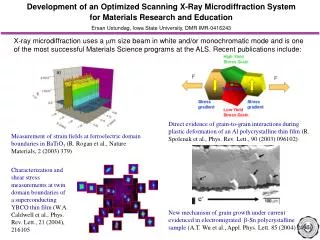
Probing magnetism and ferroelectricity with x-ray microdiffraction Paul Evans, University of Wisconsin evans@engr.wisc.edu October 9, 2002
Outline • Magnetic and Polarization Domains in Solids • Hard X-ray Microdiffraction • Antiferromagnetic domains and the “spin-flip” transition in chromium • Polarization reversal in strontium bismuth tantalate thin films • Conclusions
Example 1: Polarization domains in ferroelectrics • TEM study of BaTiO3 A. Krishnan, M. E. Bisher, and M. M. J. Treacy, Mat. Res. Soc. Symp. Proc. 541 475 (1998). towards bulk
2 m Resistivity and magnetoresistance depend on domain configuration in micron-scale Fe wires. Example 2: Magnetic domain wall resistance in Fe H transverse H transverse H longitudinal H longitudinal Ruediger et al., Phys. Rev. Lett. 80 5639 (1998).
zone plate D~100 m Focusing X-rays Using Zone Plates order sorting aperture f~10 cm L~50 m Source demagnified by L/f500. • 6 to 30 keV • 1010 ph/s/0.01%BW • Flux Density Gain - 105 • Minimum spot - 0.15 x 0.15 µm2
Hard X-ray Machine: Advanced Photon Source Chicago 30 miles Argonne Natl. Lab. Murray Hill 700 miles 350 m
5 m 2 (deg.) in 2 scans distance from g. b. (m) X-ray Microprobe Applications Glasses for fibers, amplifiers: Dopant Distributions (with R. Windeler, Lucent/OFS, and J. Maser APS) Yb x-ray fluorescence fiber amplifier core Strain relaxation in LaSrMnO film on a bicrystal substrate Y.-A. Soh, et al., submitted. Strain at an artificial grain boundary 0.1 Å-1
10 m 3 m X-ray Microprobe Applications periodically poled LiNbO3 polarization domains switching in a SrBi2Ta2O9 thin film capacitor Domains in ferroelectric materials Spin density wave domains in Cr P. G. Evans, et al., Science 295 1042 (2002). Magnetic x-ray microscopy 100 m
Spin density wave domains in chromium Cr is a spin density wave (SDW) antiferromagnet. • SDW leads to strain wave and charge density wave (CDW). • Spins are transverse T=123 to 311 K, longitudinal for T<123 K. • Domains are responsible for macroscopically observable magnetic, mechanical, electrical phenomena. • Previous domain imaging experiments are at the 1 mm scale. Q || [001] Cr unit cell • Antiferromagnetic Domains: • Modulation direction Q any <001> • Three possible Q domains. • Spin polarizations S, also <001> • Two S domains in transverse phase. • Just one S (||Q) in longitudinal phase. S || [100]
Fermi surface nesting in Cr Difficult to calculate (q) directly, but common feature is (q) susceptibility, response of hypothetical non-magnetic system to magnetic perturbation with wavevector q QSDW where EK+q and EK are pairs of filled and empty states differing in wavevector by q. Band structure of Cr: Fermi surfaces nest with Q=(0,0,1-) , incommensurate with lattice.
Domain effects in chromium (?) Magnetoresistance of a Cr thin film is enhanced below spin flip transition. Mattson et al. J. Magn. Magn. Mater. 109 179 (1992). Magnetoresistance reaches 50% at 4K for H=5 T.
(Non-Resonant) Magnetic X-ray Scattering: Classical Picture Force Radiation -e “Thomson scattering” -eE electric dipole E E -e magnetic quadrupole -eE H E -e electric dipole E H -e magnetic dipole After F. de Bergevin and M. Brunel, Acta Cryst. A 37 314 (1981). H H
Cr in reciprocal space Magnetic scattering appears near forbidden lattice reflections. Also: Strain wave (CDW) reflections near allowed lattice reflections. K H L SDW near (0 0 1) CDW near (0 0 2) Form images using either type of reflection.
Magnetic cross sections ( polarizations. ) are equal for transverse Sample Orientation
Non-resonant magnetic x-ray diffraction from Cr Most important term of cross section scales as: Polar plot of cross section as a function of spin direction for a Q || (001) domain in our geometry.
k’-k || Cr (0 0 1-d) APS Station 2ID-D
All three Q domains are present Visit one CDW reflection from each family. h scan near (2 0 0) k scan near (0 2 0) l scan near (0 0 2) Room temperature laboratory diffractometer scans with large mm-scale beam.
SDW magnetic reflection SDW Domains at 130 K CDW charged reflection incident beam h=5.8 keV incident beam h=11.6 keV
Spin-flip transition Transverse SDW phase Longitudinal SDW phase TSF=123 K in bulk Cr Image SDW reflection as a function of temperature. Magnetic reflection disappears!
Repeat with charged CDW reflection SDW Magnetic reflection CDW Charged reflection T=130 K T=130 K T=110 K T=110 K
Spin flip transition begins at Q domain edges Nominally first order transition is broadened by several degrees, even at micron scale.
Sources of broadening Magnetic effects at ferromagnet/antiferromagnet interfaces are well described in comparison. Not much known (yet) about antiferromagnetic domain walls. 1. Magnetic interactions across domain boundary. Q Q S S vs. Q S Q S 2. Fermi surface effects. Simultaneous Fermi surface nesting at multiple Q directions is not allowed. 3. Strain, impurities, defects. Challenges: length and energy scales, several types of domain walls.
Learning more about domain walls 1) So far we’ve looked at Q || [001]. What happens in neighboring Q domains? K red Q || [100] green Q || [010] blue Q || [001] H L SDW near (0 0 1) CDW near (0 0 2) 2) Two spin polarizations within transverse phase.
Magnetic cross sections in a Q || [100] domain transverse phase S || [010] longitudinal phase S || [100] diffracted beam k’ incident beam k transverse phase S || [001] Cross section with S along [100] or [010] than along [001].
S domains within a [100] Q domain 10 mm Image (,0,1) reflection. 110 K 125 K 140 K S: longitudinal mixed transverse S || [001] || Q or S || [010] Q visible spins: S || [001] || Q S || [010] Q Next steps: What’s happening in adjacent domain? Width of S domain wall?
Cr Summary • Self organized or artificial domains at small scales are key to macroscopic properties. Imaging is important. • Spin flip transition in Cr begins at domain walls upon cooling. • Future work in Cr: • Control of domain walls • Spin polarization relationships across domain walls? • Separation of bulk and interface effects • Thin films
Ti O c=1.01 a Ba a=3.995 Å Ferroelectric materials • Example: tetragonal phase of barium titanate (BaTiO3) • 6 possible polarizations • Organized naturally or artificially into domains. Ps=26 C cm-2 What can be learned about polarization switching in ferroelectric materials? Problems with existing techniques: time resolution, electrodes, quantification.
First Step: Strontium Bismuth Tantalate Thin Film Devices P=18.2 C/cm2 Built-in polarization is along crystalline a-axis. Grow films with surface normal not along c-axis. k q || (1 1 6) k’ 100 nm Pt electrode Vapplied 250 nm SrBi2Ta2O9 SrTiO3 (110) substrate
Imaging Domains by Breaking Friedel’s Law Four types of domains: (+) (+) (-) (-) c b (116) a Intensity of SrBi2Ta2O9 reflection is different for (+) and (-). contrast of (2,2,12) “flipping ratio” (I(+)-I(-))/(I(+)+I(-)) Ta L3 resonance 9.8835 keV Incident beam energy (keV)
Image Polarization Switching 20 m 3 m Map SBT (2,2,12) reflection following voltage pulses to top electrode. = - after +8V after -8V –4V +4.4V +5.2V +6V +8V –8V then:
0 7.5 Peak Voltage Structural Constrast is Quantitative Films reach electrical breakdown before the ferroelectric polarization is completely switched.
Conclusions • New tools for materials where domains and interfaces are important: • Antiferromagnetic domains and the spin flip transition in Cr • New microscopy for ferroelectric materials • Strain relaxation at artificial grain boundaries • Future: time resolved measurements, lower T, applied fields…
People • Eric Isaacs, Glen Kowach, John Grazul, Lucent • Gabe Aeppli, Yeong-Ah Soh, NEC • Barry Lai, Zhonghou Cai, Eric Dufresne, Advanced Photon Source • Alain Pignolet, Ho-Nyung Lee, Dietrich Hesse, MPI Halle