Download

1 / 35
350 likes | 532 Vues
Materials for CSQ. PM: Karl Roenigk, IARPA PI: David P. Pappas, NIST Staff: Danielle Braje, Robert Erickson, Fabio da Silva, Jeff Kline IC Postdoc - David Wisbey Collaboration : CU Denver: H. Fardi, M. Huber Colorado School of Mines – Brian Gorman, Mike Kaufman.

E N D
Materials for CSQ PM: Karl Roenigk, IARPA PI: David P. Pappas, NIST Staff: Danielle Braje, Robert Erickson,Fabio da Silva, Jeff Kline IC Postdoc - David Wisbey Collaboration : CU Denver: H. Fardi, M. Huber Colorado School of Mines – Brian Gorman, Mike Kaufman
Outline • Ongoing theoretical work: • Analyze junction response • DC and AC • Simulate absorption of materials • Potential work: • Atomistic calculations of interface structure • Need cubic spinel sturctures as templates • Steve Helberg – NRL • Q reference material ILC? • Q is a function of temperature and power • Q is high at high T & P, low at low T&P • Qubits operate at low T & P • RM is critical to define milestones of program
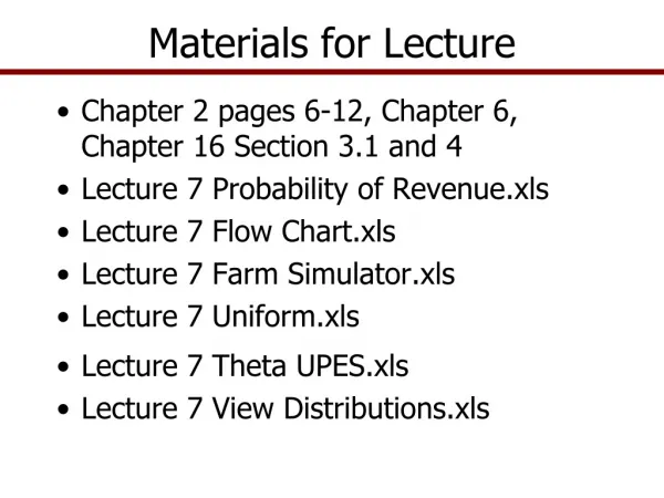
Example: sapphire/Al(111)/Al2O3/Al(111) T=1.8K Trilayer flowchart Substrate Need ADR For TLS analysis RF? RHEED? AFM? Bottom Electrode Need ADR TC Al <1.8 K RHEED? AFM/STM? RF? Tunnel Barrier RHEED? AFM? Top Electrode CIPT shows shorted junction CIPT TEM, AFM Thy Process junction CAFM Thy Insulator, wiring RF IV T1,T2 Thy
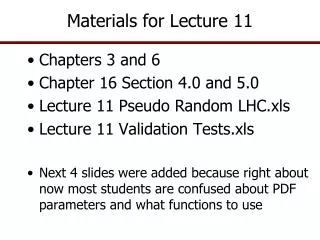
Epitaxial Junction Problem S.C. Oxide S.C. • Tunneling barrier interface defects: • random roughness (O diffusion within Al overlayers), • terraces (epitaxially produced) • pinholes S.C. Oxide S.C. Oxide S.C. Al Oxygen Diffusion Terraces Pinholes
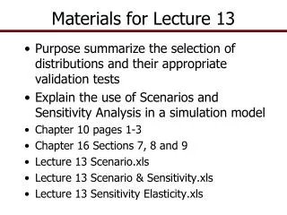
Example:Al(111)/epi-Al2O3/Al(111) structure on sapphire TEM Brian Gorman CSM FIB Pt Oxide / Al / Re Epitaxial Al Sapphire Substrate
HRTEM of Oxide Layer 0.37nm Top Al(111) Oxide Al2O3 0.23nm <111> Al <111>Al <0001> Al2O3 Epi Al(111)
Approach • Development of quick and efficient procedure for detecting junction interface defects • Electrical IV measurements (DC) • Barrier tunneling model • account for subharmonic energy-gap structure • assess interface defects, particularly pinholes • Electric RF absorption (AC) • Engineered Fe+3 magnetic impurities • Probes of terracing & thickness deviations
x S I S d2 d1 Barrier Tunneling Model • Applicable to S-I-S geometry [Arnold] • Tunneling current formalized using non-equilibrium single-particle Green functions [Keldysh] • Non-transfer Hamiltonian—transmission probability T2 included to all orders [Feuchtwang] (first principles equivalent)
2 - e 2 - 3 CP 1 = - e CP 2 = 0 - h - (evanescent) S I S Multiple Andreev Reflection (eV = - ) Barrier Tunneling Model • Subharmonic gap structure (barrier contribution) • MAR: Multiple Andreev Reflection [KBT] • MPT: Multi-Particle Tunneling [Shrieffer and Wilkins] • MAR accounts for voltages below threshold /e, which are not addressed by MPT
e 2 +3 2 + 1 = + e CP 2 = 0 h - - (evanescent) S I S Multiple Andreev Reflection (eV = + ) Barrier Tunneling Model • Voltages above threshold /e
Barrier Model and Pinholes • Example applied to Nb/AlOx/Nb tunnel junctions [Kleinsasser] • Subgap current attributable to multiple Andreev reflection • Extended to account for pinholes via parameters: • Pinhole transmission probability T2 (near unity, by definition) • Ratio of pinhole conductance to that of barrier 4% of current due to pinholes (T2 ~ 1)
z Al z(x,y) Al-O z(x,y)=d Fe3+ x Al Fe3+ Probes of Roughness • Fe3+ impurities can be used as probes of junction interface roughness when microwaves are applied ,V0 • By Faraday’s law, roughness induces a driving magnetic induction that couples to Fe3+ impurities • For example, Fe3+ power absorption depends on the variance of this induction (ħ0 ~ 12 GHz)
How Fe3+ Impurities Couple to Junction Phase Qubit z d<<R d JJ Fe3+ R • Phase of Cooper-pair wave function is shifted by Fe3+ impurities in single-crystal sapphire junction* • This introduces time-independent interaction terms in the washboard potential of the Hamiltonian • Provides mechanism for decoherence and 1/f noise * R.P. Erickson and D.P. Pappas, “Model of magnetic impurities within the Josephson junction of a phase qubit”, Submitted to PRB Rapid Comm. 16
Progress • Barrier tunneling model • Correspondence with G. Arnold; source code provided • Initial implementation to be completed June 1, 2009 • Next step: application to NIST I-V measurements • Then extend model to include terrace-induced channels • Fe3+ probes of roughness • Initial theory development completed April 1, 2009 • Next step: application to NIST measurements • Then extend model to self-consistency within London gauge
Nature of the faults in Al(111) on sapphire Faults in epi Al initiate at substrate, are transferred vertically through the Al to the oxide layer, near where the growth abnormalities seem to form in most cases
Dark Field Imaging of Faults in Al(111) on sapphire Left: 2-beam bright field image using the 006 reflection shown in the inset SADP Right: CDF image using the same 006 reflection as in the left image Note that the top layer of Al are not illuminated using this reflection, indicating that the bright areas in the CDF image are slightly misoriented in-plane
Slightly tilt sample: Left: 2-beam bright field image using the 006 reflection shown in the inset SADP Right: CDF image using the 006 reflection as in the left image, Note the top layer of Al are not illuminated, indicating that the bright areas in the CDF image are slightly misoriented in-plane with respect to the previous 006 CDF image
Basal Plane Sapphire Atomic Placement Al(111) Sapphire Atomic positions of the Al (pink) and O (gray) for sapphire oriented down the basal plane. Note the rotation of the oxygen atoms in the c-direction of the crystal
Potential solution • Change substrate to cubic spinel • e.g. MgAl2O4 (111) • Lattice matched between Al & Al2O3 • No staggered O atom sub-lattices • High T material • Suggest simulating superconductor-spinel interface • Potential NRL contribution
LCR electrical model for phase qubit LJ~sinf CJ~1-100 x10-12 Rjunction – non-linear QP tunneling Rdielectric – bound dipole relaxation Junction & insulators = G(V) Intensity What can be quantified? • Quality factor – Energy stored/Energy lost/cycle • Q = = w0/Dw • T1 = Q/w0 • Delectric loss tangent = 1/Q • tand = Im(e)/Re(e) frequency
Test dielectrics with simple LC & CPW circuits O’Connell, APL (2008) LC – parallel plate C CPW C L
CPW simulations Model field around center conductor Electric Field around CPW • Absorption in dielectric reduces Q • Primary absorption due to two-level fluctuators • Active at low T & Pwr
Saturation of TLSs at low T & P PPMS ADR |e |e wRF |g |g 10% effect @ 1.8 K 80% effect @ 0.1 K
Quality factor can appear higher due to poor T and Pwr control Increasing T Increasing P 1/Q =
Cryogenic Measurement Standard Measurements of all labs are not created equal Q appears higher for high Temperature & Power • Objectives: • Standardize inter-laboratory results • Set the bar for superconducting coherent measurements • Approach • Design test samples, which are relevant to the field • High Q CPWs for single frequencies • T & Pwr dependence • RF resonator combs for full transfer function • Fabricate AND measure samples at NIST • Conduct Inter-laboratory Comparison (ILC) • Generate SRM for community • Methods • State-of-the-art superconducting circuit test facility • Perfect Quality Factor measurements • Traceable to NIST standards (frequency and voltage) • Vision • Give researchers SMA box with calibration standard Q = “To provide for the dissemination of an internationally consistent, accurate, reproducible, and measurable cryogenic measurement standard”
Summary • Ongoing theoretical work: • Analyze junction response • DC and AC • Simulate absorption of materials • Potential work: • Atomistic calculations of interface structure • Need cubic spinel sturctures as templates • Steve Helberg – NRL • NIST Q-factor SRM • Q is a function of temperature and power • Q is high at high T & P, low at low T&P • Qubits operate at low T & P • RM is critical to define milestones of program
HPD ADR delivered & cooled • Agilent 20 GHz VNA ordered • Wiring for • 32 test junctions (4x25 pin) • 1 resonator (2 SMA) • Demonstrated T < 50 mK • Will enable in-house: • Sub-gap structure in epitaxial tunnel junctions • Process controll • Q-measurements at Low T, P to measure TLS’s
Opportunities & Issues • NIST Leverage • B1E Cleanroom B1E being installed • Can get significant space & leverage • Deposition systems, low noise space • Chlorine etch coming on line • Quantum information high priority Action Items • New techniques • Ellipsometry • Fe impurities at barriers to evaluate roughness • ADR – Lower temperature & TLS evaluation • Flip chip • Design SQUID & qubits • Stay on track with GANTT chart
Capres CIPT – NIST12-tip probe Re(10 nm) Al(10) Barrier Re or Al(150) Top surface must be conductive (Au, RuO, Re)
Percent of total energy in dielectric (50 micron trench depth )
Model: Ideal CPW – lossless Prelim Data 1.8 K
RF Substrate Evaluation Through Q T = 1.8 K • Q ~ 105 for Si, sapphire • Q decreases at lower RF power (~ 103 photons) • Influence of two-level systems • Next step: go to low temp & power with Al, Re in ADR