Download

1 / 37
370 likes | 378 Vues
This document discusses the wiring scheme for the Signal Committee Meeting on February 5, 2013. It covers topics such as address configuration, communication setup, laptop configurations, and layout issues.

E N D
Signal Committee Meeting February 5, 2013 1 1/8/2020
Wiring scheme WEST EAST Front 2 1/8/2020
Corner Modules Single Gapped(Signal Gap) JoinerTracks Double Gapped(Power Gap) Single Gapped(Signal Gap) 3 1/8/2020 JoinerTracks
Mainline Wiring 4 1/8/2020
Terminal Strip Color Conventions 5 1/8/2020
C/MRI & Xpressnet • C/MRI boards require a 5v regulated power supply with a common ground • Each board has an unique address configured using a dip switch. Currently, the corners are addresses 1, 2, 3, & 4. • We need to standardize assignment & maintenance of addresses. A maximum of 128 boards is supported. • Baud rate for communication is set to 57,600 • A USB to Serial driver is required on the computer • Computer connects wirelessly to the Lenz LAN-USB. The Lenz software to support serial connection does not work. The connection is via the IP address of the Lenz device directly which is simpler and works well. • We have two laptops configured. Both have the most recent versions of JMRI (3.2). The CATS 3.2 compatible files for Designer (2.33) and CATS (2.13) are loaded. CATS controls the versioning. CATS versions will always trail JMRI releases. Do not upgrade JMRI until CATS can support the version. 6 1/8/2020
The Circular Layout Test 7 1/8/2020
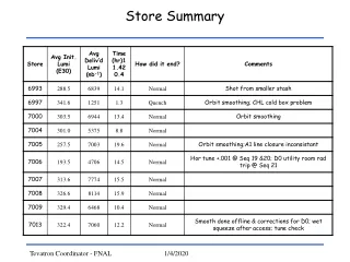
Reduced Sensitivity Found 8 1/8/2020 Baseline Voltage connected = 5.20v, unconnected = 5.74v
BD20 Reduced Sensitivity “Usual” BD20 Wiring HUB BD20 Wiring 9 1/8/2020
Wenham 2013 Layout 10 1/8/2020
How it should look 11 1/8/2020
How it did look 12 1/8/2020
How it looked after reducing DB-20 sensitivity 13 1/8/2020
The Issue The ditzels propagate power correctly but all the ditzels are constantly show ON (occupied) and thus all the blocks between corner modules are ON even when unoccupied. The two short segments on each module function correctly. 14 1/8/2020
Test Desensitizing BD20s 15 1/8/2020
The DDCOD • The enhancements associated with the Rev. E design are: 1. Increased sensitivity to resistance across the rails, i.e. actual block occupancy 2. Minimized susceptibility to false occupancy caused by stray pickup from track wiring to other blocks, that may be running closely parallel with the detected block • Another way of looking at the situation is that Rev. E improves detection performance in the presence of electrical noise and interference from wiring to adjacent blocks. • It requires a single +12Vdc supply rather than the balanced ±12Vdc required by the OD. • Its sensitivity is easy to adjust with a trim potentiometer, using the monitor LED. • Its built-in turn-on delay of .25s and turn-off delay of 3.5s greatly reduces problems from dirty track and other causes of intermittent contact. 16 1/8/2020
Comment at the Gartner Site 17 1/8/2020 http://www.wiringfordcc.com
Detection: Next Steps • Link a long segment of flex track and test with a BD20 to see if long track segments. • Link several (3-5) passive modules and add a BD20 to see if long module segments are a problem. These have ballast and multiple wire drops. • Test BD20 desensitization with a 5-10k potentiometer • Repeat the same tests with DDCODs. • Build a sensitometer to determine minimum resistance for detection as described by Chubb. • Buy copies of the Chubb manuals. 18 1/8/2020
WiThrottle Issues • Router issues • New Router. Possible settings issues. Some routers require a connection with the internet. • May have corrupted security files on the PCs • WiThrottle Dropout • Has been reported in the listserve according to Ken Cameron. Not supposed to be an issue with the most recent version. • Ken Cameron suggested a test to do at each setup. Start a virtual throttle from the laptop and prove it’s stable prior to moving to WiThrottle. • The bottom line question is: Is this a JMRI issue or is this a communications issue? • WiFi password: 0123456789 19 1/8/2020
Resisted Wheelsets • Begin the planning process • When to we start making these and how? RailFun night? Night at Shacks? Is typically a 2 day process so this is tricky. • We will need written instructions downloadable from the website. • What is the optimal resistance? • How many axles? • What fraction of cars need resistors? Best answer is 100% but that may not be possible. 20 1/8/2020
Designer Training • Shack’s site would be ideal • I can handle 8-10 people at my house • The good news is that Rodney Black’s documentation is in Word • The bad new it’s 90 pages long • Short 1 hour sessions so people could get started and use the Word document as a reference source seems prefferable 21 1/8/2020
Designer Conventions • Active Size: 10 rows by 12 columns • Passive Size: 10 rows by 6 columns • Module Name in row 10, column 3 (passive) or column 6 (active) • Name Position is Low Centered • Inner Track is in row 8 • Outer Track is in row 9 • Avoid block sizes of 1 cell 22 1/8/2020
Designer Appearance 23 1/8/2020
Designer Definitions 24 1/8/2020
Load it into CATS 25 1/8/2020
Careful Documentation Turnout Definitions Signal position Block Definitions East Signal Definitions West Signal Definitions Signal Aspect Definitions 26 1/8/2020
TippleChubb Board Address = 1 TRACK Segment Outer 1 Block Name: Tipple OM-E – TS1 Station: Tipple Signal Discipline: ABS Occupied: Address: CS 1002 Position: Close Unoccupied: Address: CS 1002 Position: Throw TRACK Segment Outer 0Undefined Outer Main Ditzel TRACK Segment Inner 3 (active East ditzel) Block Name: Tipple IM-W – TS3 Station: Tipple Signal Discipline: ABS Occupied: Address: CS 1001 Position: Close Unoccupied: Address: CS 1001 Position: Throw TRACK Segment Outer 2 Block Name: Tipple OM-E – TS2 Station: Tipple Signal Discipline: ABS Occupied: Address: CS 1004 Position: Close Unoccupied: Address: CS 1004 Position: Throw TRACK Segment Inner 1 Block Name: Tipple IM-W – TS1 Station: Tipple Signal Discipline: ABS Occupied: Address: CS 1005 Position: Close Unoccupied: Address: CS 1005 Position: Throw TRACK Segment Inner 2 Block Name: Tipple IM-W – TS2 Station: Tipple Signal Discipline: ABS Occupied: Address: CS 1003 Position: Close Unoccupied: Address: CS 1003 Position: Throw TRACK Segment Outer 3 (active West ditzel) Block Name: Tipple OM-E – TS3 Station: Tipple Signal Discipline: ABS Occupied: Address: CS 1006 Position: Close Unoccupied: Address: CS 1006 Position: Throw TRACK Segment Inner 0Undefined Inner Main Ditzel
PastureChubb Board Address = 2 TRACK Segment Outer 1 Block Name: Pasture OM-E – TS1 Station: Pasture Signal Discipline: ABS Occupied: Address: CS 2002 Position: Close Unoccupied: Address: CS 2002 Position: Throw TRACK Segment Outer 0Undefined Outer Main Ditzel TRACK Segment Inner 3 (active East ditzel) Block Name: Pasture IM-W – TS3 Station: Pasture Signal Discipline: ABS Occupied: Address: CS 2001 Position: Close Unoccupied: Address: CS 2001 Position: Throw TRACK Segment Outer 2 Block Name: Pasture OM-E – TS2 Station: Pasture Signal Discipline: ABS Occupied: Address: CS 2004 Position: Close Unoccupied: Address: CS 2004 Position: Throw TRACK Segment Inner 1 Block Name: Pasture IM-W – TS1 Station: Pasture Signal Discipline: ABS Occupied: Address: CS 2005 Position: Close Unoccupied: Address: CS 2005 Position: Throw TRACK Segment Inner 2 Block Name: Pasture IM-W – TS2 Station: Pasture Signal Discipline: ABS Occupied: Address: CS 2003 Position: Close Unoccupied: Address: CS 2003 Position: Throw TRACK Segment Outer 3 (active West ditzel) Block Name: Pasture OM-E – TS3 Station: Pasture Signal Discipline: ABS Occupied: Address: CS 2006 Position: Close Unoccupied: Address: CS 2006 Position: Throw TRACK Segment Inner 0Undefined Inner Main Ditzel
BallgameChubb Board Address = 3 TRACK Segment Outer 1 Block Name: Ballgame OM-E – TS1 Station: Ballgame Signal Discipline: ABS Occupied: Address: CS 3002 Position: Close Unoccupied: Address: CS 3002 Position: Throw TRACK Segment Outer 0Undefined Outer Main t Ditzel TRACK Segment Inner 3 Block Name: Ballgame IM-W – TS3 Station: Ballgame Signal Discipline: ABS Occupied: Address: CS 3001 Position: Close Unoccupied: Address: CS 3001 Position: Throw TRACK Segment Outer 2 Block Name: Ballgame OM-E – TS2 Station: Ballgame Signal Discipline: ABS Occupied: Address: CS 3004 Position: Close Unoccupied: Address: CS 3004 Position: Throw TRACK Segment Inner 1 Block Name: Ballgame IM-W – TS1 Station: Ballgame Signal Discipline: ABS Occupied: Address: CS 3005 Position: Close Unoccupied: Address: CS 3005 Position: Throw TRACK Segment Inner 2 Block Name: Ballgame IM-W – TS2 Station: Ballgame Signal Discipline: ABS Occupied: Address: CS 3003 Position: Close Unoccupied: Address: CS 3003 Position: Throw TRACK Segment Outer 3 Block Name: Ballgame OM-E – TS3 Station: Ballgame Signal Discipline: ABS Occupied: Address: CS 3006 Position: Close Unoccupied: Address: CS 3006 Position: Throw TRACK Segment Inner 0Undefined Inner Main Ditzel
Twin PeaksChubb Board Address = 4 TRACK Segment Outer 1 Block Name: Twin Peaks OM-E – TS1 Station: Twin Peaks Signal Discipline: ABS Occupied: Address: CS 4002 Position: Close Unoccupied: Address: CS 4002 Position: Throw TRACK Segment Outer 0Undefined Outer Main Ditzel TRACK Segment Inner 3 (active East ditzel) Block Name: Twin Peaks IM-W – TS3 Station: Twin Peaks Signal Discipline: ABS Occupied: Address: CS 4001 Position: Close Unoccupied: Address: CS 4001 Position: Throw TRACK Segment Outer 2 Block Name: Twin Peaks OM-E – TS2 Station: Twin Peaks Signal Discipline: ABS Occupied: Address: CS 4004 Position: Close Unoccupied: Address: CS 4004 Position: Throw TRACK Segment Inner 1 Block Name: Twin Peaks IM-W – TS1 Station: Twin Peaks Signal Discipline: ABS Occupied: Address: CS 4005 Position: Close Unoccupied: Address: CS 4005 Position: Throw TRACK Segment Inner 2 Block Name: Twin Peaks IM-W – TS2 Station: Twin Peaks Signal Discipline: ABS Occupied: Address: CS 4003 Position: Close Unoccupied: Address: CS 4003 Position: Throw TRACK Segment Outer 3 (active West ditzel) Block Name: Twin Peaks OM-E – TS3 Station: Twin Peaks Signal Discipline: ABS Occupied: Address: CS 4006 Position: Close Unoccupied: Address: CS 4006 Position: Throw TRACK Segment Outer 0Undefined Inner Main Ditzel
Signal types • The module group standard will be thethree triangular light G-Type signal withany number of heads. Green on the right. • However, based upon modeler preference,any physical signal type is acceptable. • Electrically, we will only support common anode, lighting one LED or bulb per output. Common anode B&O or PRR signals are find. Bipolar LEDs for searchlights are strongly discouraged. They can be made to work as can common cathode signals but with considerable effort that will come only from the module owner. • We are considering and working on approaches to removable plugs. Currently nothing formal to report 31 1/8/2020
Corner Signals • Certainly lend themselves to ABS (intermediate) signals more than control points • Tipple may even be better without signals given it is commonly close proximity to Tipple West & Upton Throat • Signal location choices are constrained by the location of the gaps • Tomar double headed might be goodList price is $49.70. One on each mainline 32 1/8/2020
Commercial Signals NJ International Tomar Oregon Rail Supply (KITS) #1053$32.99 #1056$36.99 #H-855$26.30 #H-865$49.70 #116 $11.95 #538 $19.95 #1054$34.99 Common Cathode Custom Signal (Atlas) South Bend Integrated Signal Systems SB-G$20.00 #235$34.95 #238$44.95 #239$44.95 33 1/8/2020
Vendor Websites • BLMA: http://www.blmamodels.com • Custom Signals: http://www.customsignals.com • Integrated Signal Systems: http://www.integratedsignalsystems.com • NJ International: http://www.njinternational.com • Oregon Rail Supply: http://www.oregonrail.com • South Bend Signal Co: http://www.sbsignal.com • Tomar: http://www.tomarindustries.com/signals.htm 34 1/8/2020
Turnouts & Track • Preferably mainline turnouts should be DCC controlled. (from the DCC Accessory Bus). This is especially true for crossovers. • At present we do not have a preference for accessory decoder type. • Turnout Accessory addresses must be controlled and assigned by the Superintendent and recorded • Third track can show occupancy but does not feed occupancy information across a module boundary 35 1/8/2020
Switch-It Orange/Black Pair 36 1/8/2020
Thanks 37 1/8/2020