Download
1 / 18
280 likes | 585 Vues
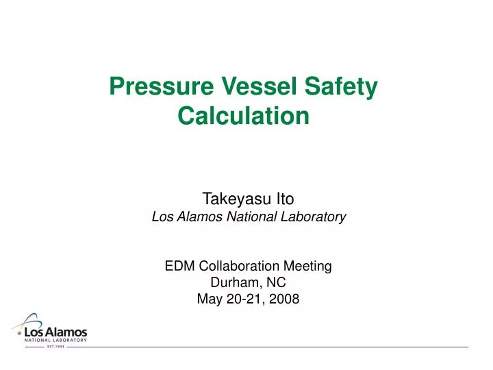
Pressure Vessel Safety Calculation. Takeyasu Ito Los Alamos National Laboratory EDM Collaboration Meeting Durham, NC May 20-21, 2008. Introduction. Cryostat needs to meet the safety requirements of the facility Recent examples Liquid hydrogen target for the SAMPLE experiment at MIT-Bates

E N D
Pressure Vessel Safety Calculation Takeyasu Ito Los Alamos National Laboratory EDM Collaboration Meeting Durham, NC May 20-21, 2008
Introduction • Cryostat needs to meet the safety requirements of the facility • Recent examples • Liquid hydrogen target for the SAMPLE experiment at MIT-Bates • Liquid hydrogen target for the G0 experiment at JLAB • Superconducting magnet for the G0 Experiment at JLAB • Liquid hydrogen target for the NPDGamma Experiment at LANL and ORNL/SNS • The nEDM apparatus needs to meet the safety requirements of ORNL/SNS. In addition, the portion of the nEDM apparatus to be first tested at LANL needs to meet the LANL safety requirements. • This is a summary of what we did for the Dual Use Cryostat. • More details can be found in the Design Document posted on the Twiki site.
Some useful references • W.M.Schmitt and C.F.Williamson, “Boiloff rates of cryogenic targets subject to catastrophic vacuum failure”, Batess Internal Report #90-02 (1990) • NPDGamma liquid hydrogen target engineering document (2007) • G.Cavallari, I.Gorine, D.Guesewell, R. Stierilin, “Safety tests with the LEP superconducting cavity”, CERN/ER/RF (1989) • Physics division cryogenic safety manual, Argonne National Laboratory Physics Division Cryogenic Safety Committee (2001).
Dual Use Cryostat Selected parameters 3He Atomic Beam Source 3He Injection Test Apparatus HV Test Apparatus HV electrodes HV LHe Volume HV Heat Shields
Credible Accident Scenarios • Loss of isolation vacuum to air or helium • Failure of liquid helium containing vessels
P He gas AIR Q Q Q Q Q AIR FREEZES Loss of isolation vacuum to air Relief valve Outer Vacuum Vessel Liquid Helium Vessel
Sizing the relief system: things to do • Estimate the rate of heat transfer to liquid helium • Determine the boiloff rate • Calculate the pressure drop • Calculate the strength of the vessel
Frozen air Film boiling Rate of heat transfer to liquid helium due to loss of vacuum Vessel wall • The rate of heat transfer depends on: • Rate of air flow • Heat resistance due to • Vessel wall • Helium gas film • Frozen air layer LHe
Rate of heat transfer to liquid helium: some measured values We adopt: with superinsulation Note: thermal conductivity of gas filled superinsulation is 7x10⁴W/m/K, which gives a heat flux of 2000 W/m2 when subject to a 300 K temperature difference.
Boiloff Rate • Helium latent heat: • Total heat flow into LHe vessel: • Helium mass flow:
Pressure Buildup • Darcy’s formula: • Resistance coefficient • Straight pipe • For turbulent flow in a smooth pipe • “Minor corrections”: correction for entrance, exit, bend, etc. f = friction factor L = length of the pipe Re= Reynolds number
MAWP (Maximum Allowable Working Pressure) • Definition given by ASME Boiler and Pressure Vessel Code Section II Part D • In general, MAWP is a pressure which raises the membrane stress in the metal to the lesser of the following two value: • the tensile strength/3.5 • the 0.2% yield strength/1.5.
Rupture disk (3”, 12 psi) Parallel plate (3”, 6 psi) Emergency vent stack Relief valve 3.0” OD pipe Primary vent stack 20” 12” Liquid Helium Vessel 27” 26” Outer Vacuum Vessel
Pressure Buildup in Dual Use Cryostat • Darcy’s formula: • Resistance coefficient • Pressure drop
Comment by Bob Bourque (head of the LANL Pressure vessel committee)
Remarks • Heat capacity of gas not taken into account • Taking the gas heat capacity into account might reduce the estimated boil off rate. • However, estimating how much heat goes into heating the gas is very difficult. • There are many approximations and they are on the side of safety, costing in heat load. If a more accurate estimate is necessary, we might need to use CFD calculation, such as FLUENCE.