Download
1 / 52
590 likes | 1.17k Vues
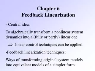
Feedback Control Theory a Computer System’s Perspective. Chenyang Lu Department of Computer Science University of Virginia chenyang@cs.virginia.edu http://www.cs.virginia.edu/~cl7v. Outline. Introduction What is feedback control? Why do computer systems need feedback control?

E N D
Feedback Control Theory a Computer System’s Perspective Chenyang Lu Department of Computer Science University of Virginia chenyang@cs.virginia.edu http://www.cs.virginia.edu/~cl7v
Outline • Introduction • What is feedback control? • Why do computer systems need feedback control? • Control design methodology • System modeling • Performance specs/metrics • Controller design • Summary
Control • Applying input to cause system variables to conform to desired values called the reference. • Cruise-control car: f_engine(t)=? speed=60 mph • E-commerce server: Resource allocation? T_response=5 sec • Embedded networks: Flow rate? Delay = 1 sec • Computer systems: QoS guarantees
Open-loop control • Compute control input without continuous variable measurement • Simple • Need to know EVERYTHINGACCURATELY to work right • Cruise-control car: friction(t), ramp_angle(t) • E-commerce server: Workload (request arrival rate? resource consumption?); system (service time? failures?) • Open-loop control fails when • We don’t know everything • We make errors in estimation/modeling • Things change
Feedback (close-loop) Control Controlled System Controller control function control input manipulated variable Actuator error sample controlled variable Monitor + - reference
Feedback (close-loop) Control • Measure variables and use it to compute control input • More complicated (so we need control theory) • Continuously measure & correct • Cruise-control car: measure speed & change engine force • Ecommerce server: measure response time & admission control • Embedded network: measure collision & change backoff window • Feedback control theory makes it possible to control well even if • We don’t know everything • We make errors in estimation/modeling • Things change
Why feedback control?Open, unpredictable environments • Deeply embedded networks: interaction with physical environments • Number of working nodes • Number of interesting events • Number of hops • Connectivity • Available bandwidth • Congested area • Internet: E-business, on-line stock broker • Unpredictable off-the-shelf hardware
Why feedback control?We want QoS guarantees • Deeply embedded networks • Update intruder position every 30 sec • Report fire <= 1 min • E-business server • Purchase completion time <= 5 sec • Throughput >= 1000 transaction/sec • The problem: provide QoS guarantees in open, unpredictable environments
Advantage of feedback control theory • Adaptive resource management heuristics • Laborious design/tuning/testing iterations • Not enough confidence in face of untested workload • Queuing theory • Doesn’t handle feedbacks • Not good at characterizing transient behavior in overload • Feedback control theory • Systematic theoretical approach for analysis and design • Predict system response and stability to input
Outline • Introduction • What is feedback control? • Why do today’s computer systems need feedback control? • Control design methodology • System modeling • Performance specs/metrics • Controller design • Summary
Control design methodology Controller Design Root-Locus PI Control Modeling analytical system IDs Dynamic model Control algorithm Satisfy Requirement Analysis Performance Specifications
System Models • Linear vs. non-linear (differential eqns) • Deterministic vs. Stochastic • Time-invariant vs. Time-varying • Are coefficients functions of time? • Continuous-time vs. Discrete-time • System ID vs. First Principle
C(s) G(s) Y(s) R(s) - Dynamic Model • Computer systems are dynamic • Current output depends on “history” • Characterize relationships among system variables • Differential equations (time domain) • Transfer functions (frequency domain) Y(s) = G(s)U(s) • Block diagram (pictorial)
Example Utilization control in a video server • Periodic task Ti corresponding to each video stream i • c[i]: processing time, p[i]: period • Stream i’s requested CPU utilization: u[i]=c[i]/p[i] • Total CPU utilization: U(t)={k}u[k], {k} is the set of active streams • Completion rate: Rc(t)= ({kc}u[m])/t, where {m} is the set of terminated video streams during [t, t+t] • Unknown • Admission rate: Ra(t)= ({ka}u[j])/t, where {j} is the set of admitted streams during [t, t+t] • Problem: design an admission controller to guarantee U(t)=Us regardless of Rc(t)
Model Differential equation Error: E(t)=Us-U(t) Model (differential equation): Controller C? E(t) Ra(t) Ra(t) - Us C? U(t) CPU Rc(t)
u(t) g(t) y(t) U(s) G(s) Y(s) A Diverge to MathSystem representations • Three ways of system modeling • Time domain: convolution; differential equations. • s (frequency) domain: multiplication • Block diagram: pictorial s-domain is a simple & powerful “language” for control analysis
A Diverge to MathLaplace transform • Laplace transform of a signal f(t) where s=+i is a complex variable. • Laplace transform is a translation from time-domain to s-domain • Differential equation Polynomial function
A Diverge to MathLaplace transform • Basic translations • Impulse function f(t)=(t) F(s)=1 • Step signal f(t)=a•1(t) F(s)=1/s • Ramp signal f(t)=a•t F(s)=a/s2 • Exp signal f(t)=eat F(s)=1/(s-a) • Sinusoid signal f(t)=sin(at) F(s)=a/(s2+a2) • Composition rules • Linearity L[af(t)+bg(t)] = aL[f(t)]+bL[g(t)] • Differentiation L[df(t)/dt] = sF(s) – f(0-) • Integration L[tf()d] = F(s)/s
U(s) G(s) Y(s) A Diverge to MathTransfer function • Modeling a linear time-invariant (LTI) system • G(s) = Y(s)/U(s) Y(s) = G(s)U(s) E.g., a second order system with poles p1 and p2
A Diverge to MathPoles and Zeros • The response of a linear time-invariant (LTI) system {pi} are poles of the function and decide the system behavior
A Diverge to MathTime response vs. pole location Stable Unstable f’(t) = ept, p = a+bj
C(s) Go(s) Y(s) R(s) - R(s) Gc(s) Y(s) A Diverge to MathBlock diagram • A pictorial tool to represent a system based on transfer functions and signal flows • Represent a feedback control system
Back to Our utilization control example Error: E(t)=Us-U(t) Model (differential equation): Controller C? E(t) Ra(t) Ra(t) - Us C? U(t) CPU Rc(t)
Rc(s) Ra(s) Go C(s) U(s) Us/s ModelTransfer func. & block diag. CPU is modeled as an integrator • Inputs: reference Us(s) = Us/s; completion rate Rc(s) • Close-loop system transfer functions • Us(s) as input: G1(s) = C(s)Go(s)/(1+C(s)Go(s)) • Rc(s) as input: G2(s) = Go(s)/(1+C(s)Go(s)) • Output: U(s)=G1(s)Us/s+G2(s)Rc(s)
Control design methodology Controller Design Root-Locus PI Control Modeling analytical system IDs Dynamic model Control algorithm Satisfy Requirement Analysis Performance Specifications
Design GoalsPerformance Specifications • Stability • Transient response • Steady-state error • Robustness • Disturbance rejection • Sensitivity
Performance SpecsStability • BIBO stability: bounded input results in bounded output. • A LTI system is BIBO stable if all poles of its transfer function are in the LHP (pi, Re[pi]<0).
Performance SpecsStability Stable Unstable
Performance specifications Controlled variable Overshoot Steady state error % Reference Transient State Steady State Time Settling time
Example: Control & Response in an Email Server (IBM) Response (queue length) Good Bad Control (MaxUsers) Slow Useless
Easy to evaluate system long term behavior without solving it Performance SpecsSteady-state error • Steady state (tracking) error of a stable system r(t) is the reference input, y(t) is the system output. • How accurately can a system achieve the desired state? • Final value theorem: if all poles of sF(s) are in the open left-half of the s-plane, then
Performance SpecsSteady-state error Steady state error of a CPU-utilization control system U(t) Us ess=-20%
Performance SpecsRobustness • Disturbance rejection: steady-state error caused by external disturbances • Can a system track the reference input despite of external disturbances? • Denial-of-service attacks • Sensitivity: relative change in steady-state output divided by the relative change of a system parameter • Can a system track the reference input despite of variations in the system? • Increased task execution times • Device failures
Performance SpecsGoal of Feedback Control • Guarantee stability • Improve transient response • Short settling time • Small overshoot • Small steady state error • Improve robustness wrt uncertainties • Disturbance rejection • Low sensitivity
Control design methodology Controller Design Root-Locus PID Control Modeling analytical system IDs Dynamic model Control algorithm Satisfy Requirement Analysis Performance Specifications
E(s) X(s) C(s) Go(s) Y(s) R(s) - Controller DesignPID control • Proportional-Integral-Derivative (PID) Control • Proportional Control • Integral control • Derivative control • Classical controllers with well-studied properties and tuning rules
Rc(s) Ra(s) Go C(s) U(s) Us/s Controller DesignCPU Utilization Control CPU is modeled as an integrator • Inputs: set-point Us(s) = Us/s ; task completion Rc(s) • Close-loop system transfer functions • Us(s) as input: G1(s) = C(s)Go(s)/(1+C(s)Go(s)) • Rc(s) as input: G2(s) = Go(s)/(1+C(s)Go(s)) • C(s)=? to achieve zero steady-state error: U(t) Us
Rc(s) Ra(s) Go C(s) U(s) Us/s Proportional ControlStability • Proportional Controller • ra(t)=Ke(t); C(s) = K • Transfer functions • Us/s as input: G1(s) = K/(s+K) • Rc(s) as input: G2(s) = 1/(s+K) • Stability • Pole p0 = -K<0 System is BIBO stable iff K>0 • Note: System may shoot to 100% if K<0!
Proportional ControlSteady-state error • Assume completion rate Rc(t) keeps constant for a time period longer than the settling time: Rc(s)=Rc/s • System response is Compute steady-state err using final value theorem, P-control cannot achieve the desired CPU utilization Us; instead it will end up lower by Rc/K Oops! The larger the proportional gain K is, the closer will CPU utilization approach to Us
CPU UtilizationProportional Control U(t) Us ess=-20%
Rc(s) Ra(s) Go C(s) U(s) Us/s Proportional-Integral ControlStability • Proportional Controller • ra(t)=K(e(t)+Ki•te()d)C(s) = K(1+Ki/s) • Transfer functions • Us/s as input: G1(s) =(Ks+KKi)/(s2+Ks+KKi) • Rc(s) as input: G2(s) = s/(s2+Ks+KKi) • Stability • Poles Re[p0]<0, Re[p0]<0 System is BIBO stable iff K>0 & Ki>0
Proportional ControlSteady-state error • Assume completion rate Rc(t) keeps constant for a time period longer than the settling time: Rc(s)=Rc/s • System response is Compute steady-state err using final value theorem, PI control can accurately achieve the desired CPU utilization Us Control analysis gives design guidance
CPU UtilizationProportional-Integral Control U(t) Mp=0 Us ess=0 ts tr tp
Controller DesignSummary & pointers • PID control: simple, works well in many systems • P control: may have non-zero steady-state error • I control: improves steady-state tracking • D control: may improve stability & transient response • Linear continuous time control • Root-locus design • Frequency-response design • State-space design • G. F. Franklin et. al., Feedback control of dynamic systems
Discrete Control • More useful for computer systems • Time is discrete; sampled system • denoted k instead of t • Main tool is z-transform • f(k) ®F(z) , where z is complex • Analogous to Laplace transform for s-domain
Discrete Modeling • Difference equation • V(m) = a1V(m-1) + a2V(m-2) + b1U(m-1) + b2U(m-2) • z domain: V(z) = a1z-1V(z) + a2z-2V(z) + b1z-1U(z) + b2z-2U(z) • Transfer function G(z) = (b1z + b2)/(z2-a1z - a2) • V(m): output in mth sampling window • U(m): input in mth sampling window • Order n: #sampling-periods in history affects current performance • SP = 30 sec, and n = 2 Current system performance depends on previous 60 sec
Root Locus analysis of Discrete Systems • Stability boundary: |z|=1 (Unit circle) • Settling time = distance from Origin • Speed = location relative to Im axis • Right half = slower • Left half = faster
Effect of discrete poles Im(s) Higher-frequency response Longer settling time Re(s) Stable |z|=1 Unstable
Feedback control works in CS • U.Mass: network flow controllers (TCP/IP – RED) • IBM: Lotus Notes admission control • UIUC: Distributed visual tracking • UVA • Web Caching QoS • Apache Web Server QoS differentiation • Active queue management in networks • Processor thermal control • Online data migration in network storage (with HP) • Real-time embedded networking • Control middleware • Feedback control real-time scheduling
Advanced Control Topics • Robust Control • Can the system tolerate noise? • Adaptive Control • Controller changes over time (adapts) • MIMO Control • Multiple inputs and/or outputs • Stochastic Control • Controller minimizes variance • Optimal Control • Controller minimizes a cost function of error and control energy • Nonlinear systems • Neuro-fuzzy control • Challenging to derive analytic results