Download
1 / 37
370 likes | 833 Vues
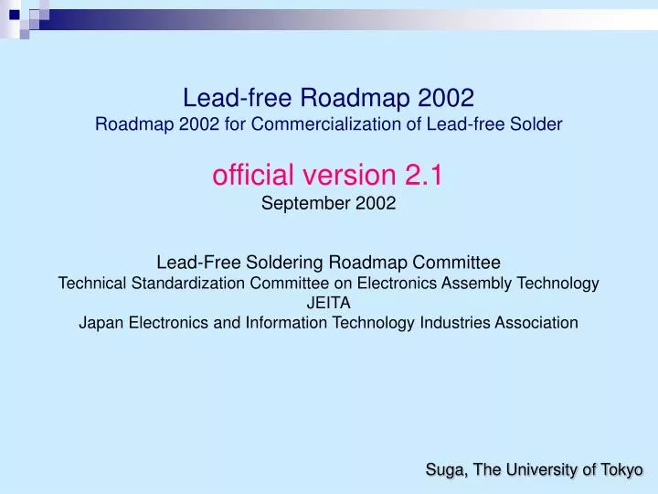
Lead-free Roadmap 2002 Roadmap 2002 for Commercialization of Lead-free Solder official version 2.1 September 2002 Lead-Free Soldering Roadmap Committee Technical Standardization Committee on Electronics Assembly Technology JEITA Japan Electronics and Information Technology Industries Association

E N D
Lead-free Roadmap 2002Roadmap 2002 for Commercialization of Lead-free Solderofficial version 2.1September 2002Lead-Free Soldering Roadmap CommitteeTechnical Standardization Committee on Electronics Assembly Technology JEITAJapan Electronics and Information Technology Industries Association Suga, The University of Tokyo
Policy in making the Lead-free Roadmap 2002 • Make the clear definition of lead-free. • Put the trends of lead-free application on a timeline. • Clearly show the leading makers and the followers. • Make the de facto standard. • Extract and promote the standardization, without picking up every factor. • Make active proposals towards the rest of the world. • Based on questionnaire survey. • February 2002, 160 answers
Roadmap 20021. Definition of Lead-free: Lead content • Definition of lead-free: In the following phases, the amount of contained Pb in the prescribed parts planned for lead-free adoption should be less than 0.1w percent. • The value must be given if it exceeds that amount. • If there is any exemption, the definition refers to the rest parts of the product, with indication of the name of the item of the exemption and the amount of contained Pb.
Roadmap 20021. Definition of Lead-free: Lead-free phase Components Equipment Phase 1 Common definition in the equipment for lead-free:No leaded solder is used at the stage of board assembly in board surface finishing, solder paste and solder bath, Components withstand heat resistance: Heat resistance against soldering in assembly with lead-free solder Phase 1 Phase 1A Equipment with lead-free solder A: Application of current components or components withstand heat resistant, Phase1 (Composing components and materials may contain lead, while the assembly solder is lead-free) Components with lead-free solder: Module components etc. Correspond to Phase1 in Equipment. Phase 2 Phase 2 Lead-free terminal components: No lead contained plating and electrodes of terminal parts of components assembled to PWB etc. The components may contain leaded composing components and materials. Equipment with lead-free solder B:Application of lead-free terminal components, Phase2, or lead-free components, Phase3 (Even if the assembled components are lead-free, the other components and materials may contain lead.) Phase 3 Phase 3 Lead-free components: No lead contained in all the internal bonding and/or composing components and materials Lead-free equipment: Application of lead-free components, Phase3, only and non leaded composing components and materials in addition to assembled components and bonding materials Phase 0 Lead-free component equipment: Application of lead-free terminal components, Phase2, or lead-free components, Phase3, with lead-bearing solder in bonding materials (Excluded from the category of lead-free equipment)
Roadmap 20022. EU-regulation and Japanese reaction • The lead-free regulation in the EU will be accepted with reluctance in Japan, if it is crucial for the environment. • In that case, the same kind of regulation should be required also in Japan. • A global agreement on the definition of lead-free and on the standard for judgment is needed as early as possible.
Roadmap 20023. Timeline for lead-free • Timeline for lead-free: Set up the schedule for the average makers as follows. • Components: • Start supplying components withstand heat resistance / lead-free terminal components: ---------------------------------------------2001 • Complete supplying of lead-free terminal components: --2003 • Complete supplying of lead-free components: --------------2004 • Equipment: • Start introducing lead-free solder: ------------------------------2002-2003 • Totally adopt lead-free solder into new products: -----------2003 • Complete lead-free adoption: ------------------------------------2005 • The “leading makers” are 1 year ahead of this schedule, and the “followers” are 2 years behind. • There is a need to establish a worldwide milestone and a roadmap.
Roadmap 20026. Standardization of lead-free solder • The following types of solder are recommended. • Board assembly:(Recommended) Sn-3Ag-0.5Cu • Reflow:Sn-3Ag-0.5Cu > Sn-Ag > Sn-Zn-Bi • Wave: Sn-3Ag-0.5Cu > Sn-Cu • Hand: Sn-3Ag-0.5Cu • Components: • Solder balls (Recommended): Sn-3Ag-0.5Cu • Land finish (Recommenced): Plating/Au, Solder precoat/Sn-3Ag-0.5Cu • Currently, more than one type are adopted to component electrodes and terminal plating as follows. • Component electrodes and terminal plating (Current situation) • Semiconductor components: : Sn-Bi plating is majority;Sn-Bi > Sn-Cu > Sn > Sn-Ag > Au-Pd • Passive components: Sn plating is the main;Sn > Sn-Cu > Sn-Bi • Terminal finishes: Sn-Cu plating and Sn plating are the majorities;Sn-Cu > Sn > Au
Roadmap 20027. Assessment standard for heat resistance of components: wave soldering • For the time being, the heat resistance standard for wave soldering is; 260C, 10 seconds.
Roadmap 20027. Assessment standard for heat resistance of components: reflow soldering • As for the temperature profile for heat resistance assessment in reflow, the equipment makers are likely to assume the ‘Hat type’ and the component makers are likely to assume the ‘Angle type’. The ‘Hat type’ is a recommendation. Hat type 30〜40s Angle type <10s 260 240〜250 220 220〜230 90s 30〜60s 180/180 150/ 150 90〜120s
Roadmap 20028. Facilities, processes, and design change • Promote lead-free adoption and energy saving by improving facilities and processes without large changes in design.
Roadmap 20029. Labeling • Promote industrial standardization of lead-free labeling.
Outline Survey (2004.Sep) A survey has been conducted to confirm the progress on lead-free implementation and associated problems. Respondents of Survey Results of Survey Assembly Manufacturers Device Suppliers Material Suppliers
Respondents of Survey Total number of manufacturers and suppliers who responded the survey: 92
Results of Survey Assembly Manufacturers Device Suppliers Material Suppliers
Results of Survey: Assembly manufacturers Q 1. Is lead-free assembly manufacturing in progress? White goods, AV information appliances, PDA, Printer, Copier: 14
Results of Survey: Assembly manufacturers (Cont’d) Q 1. Is lead-free assembly manufacturing in progress? Exchanger at base transceiver station, Industrial control equipment, Vehicle equipment, Others: 10
Results of Survey: Assembly manufacturers (Cont’d) Q 2. What are problems with lead-free implementation? White goods, AV information appliances, PDA, Printer, Copier: 14 Exchanger at base transceiver station, Industrial control equipment, Vehicle equipment, Others: 10
Results of Survey: Assembly manufacturers (Cont’d) Q 3. How much should be the allowable lead content in solder? White goods, AV information appliances, PDA, Printer, Copier: 14
Results of Survey: Assembly manufacturers (Cont’d) Q 3. How much should be the allowable lead content in solder? Exchanger at base transceiver station, Industrial control equipment, Vehicle equipment, Others: 10
Results of Survey: Assembly manufacturers (Cont’d) Q 4. Is lead-free implementation of terminals in progress? White goods, AV information appliances, PDA, Printer, Copier: 14
Results of Survey: Assembly manufacturers (Cont’d) Q 4. Is lead-free implementation of terminals in progress? Exchanger at base transceiver station, Industrial control equipment, Vehicle equipment, Others: 10
Results of Survey Assembly Manufacturers Device Suppliers Material Suppliers
Results of Survey: Device suppliers Q 4. Is lead-free implementation of terminals in progress? Semiconductor devices: 10
Results of Survey: Device suppliers (Cont’d) Q 4. Is lead-free implementation of terminals in progress? Passive components : 23
Results of Survey: Device suppliers (Cont’d) Q 4. Is lead-free implementation of terminals in progress? Connecting devices : 17
Results of Survey: Device suppliers (Cont’d) Q 4. Is lead-free implementation of terminals in progress? Transducers, Modules, and Others : 9
A car manufacturer wants lead-containing plated devices. We have to use Sn-Pb plated modules due to whisker problems. As assembly manufacturers do not approve lead-free devices, we cannot put them into mass-production. Most of the motor vehicle industry keep using Sn-Pb plated devices. Concerned about the solder joint reliability of Sn-Bi plated devices with Sn-Pb solder at their ends. Cannot use Sn-Ag-Cu Ball Grid Array (BGA) when mounting. JEDEC is tightening the criteria for thermal resistance of soldering devices. It is difficult to verify that of all the devices in mass-production in time. We need to take plenty of time to evaluate materials for devices that meet the thermal resistance for lead-free implementation. Some assembly manufacturers reject a Sn/Sn-Bi dual-layer plated device as it contains Bi. Assembly manufacturers are taking a long time to evaluate and approve lead-free devices. Some of overseas assembly manufacturers reject to use Sn-Bi plated devices, while pure-Sn plated devices may be accompanied by whisker problems. Lead-free (Sn-Ag-Cu) BGA cannot be used when mounting, as many assembly manufacturers are still using lead-containing solder paste. Results of Survey: Device suppliers (Cont’d) Q 2. What are problems with lead-free implementation? Semiconductor devices: 10
Results of Survey: Device suppliers (Cont’d) Q 2. What are problems with lead-free implementation? Passive components: 23 • Especiallyvehicle manufacturers do not want to use Sn-Bi plated devices. • Certain markets and manufacturers that do not need to comply with RoHS, ELV, WEEE directives want lead-containing plated devices. That makes us difficult to consolidate all the plating into lead-free. • It takes much time to get approval for lead-free devices used formedical equipment. • We cannot supply lead-free devices to some manufacturers due to the lack of appropriate mounting technologies and management methods at their ends. • Sn-Cu and Cu/Sn plated terminal leads are not accepted by assembly manufacturers. • The thickness of Ni plated SMD cannot meet that specified by certain assembly manufacturers. • Some assembly manufacturers haven’t decided whether to incorporate lead-free devices into their business. Even if some of them may have already decided to use lead-free devices, they need to take plenty of time to approve them before use. • Lead-free implementation varies by assembly manufacturer, and therefore we cannot consolidate all the plating into lead-free.
Presence of whisker problems with connectorsforFFC/FPC due to FFC/FPC manufacturers’ delay in taking action. Technical standards for whisker problems are too uniformed to implement. Presence of whisker problems with connectors for FPC. Alternatively, use Au plating for them. Quality criterion for lead-free devices differs by manufacturer. There’re so many varied ideas among manufacturers on the importance of lead-free implementation. Composition of solder varies depending on assembly manufacturer. Not all assembly manufacturers are making the smooth transition to lead-free devices, and they are taking a lot of time for evaluation tests of whisker problems. For overseas consumption, we have already completed lead-free implementation. For Japanese consumption, we are dealing with vehicle devices, and are making a specific plan for lead-free implementation with an eye to ELV directive. Lead-free is therefore implemented one by one upon a manufacturer’s request. As for copper land on boards, Tin lead is approved by ELV directive, and the gold-plated devices on the flow-soldering side contain lead. Major assembly manufacturers are approaching to lead-free implementation in various ways, and want us to supply them with lead-free devices with almost unfeasible specifications. The approach to and the awareness of the importance of lead-free implementation differ depending on the industry, and that causes the delay in approving lead-free devices at assembly manufacturers. We are spending plenty of time for finding alternatives to lead-containing plated devices. Results of Survey: Device suppliers (Cont’d) Q 2. What are problems with lead-free implementation? Connecting devices: 17
Approval criteria for lead-free devices varies by assembly manufacture. Some manufacturers, who sell products bearing model numbers, do not accept the change from leaded devices to lead-free ones. Vehicle manufacturers do not approve lead-free spare parts. Non-regulated industries do not require lead-free devices. A lead-free device, which we were going to use, have been made as a trial, and we don’t know when it will be put into mass-production. Assembly manufacturers are spending plenty of time for approving lead-free devices. Whisker problems have not been solved yet. Alternative materials and techniques to lead-containing plated devices are insufficient. Lead-free devices require an improved thermal resistance. Non-regulated industries, which are dealing electric components, power supply, gas supply, and disaster-prevention equipment, are very cautious about incorporating lead-free devices into their manufacturing processes. Requirements for composition of lead-free plating are varied by assembly manufacturer. Terminal lead manufacturers have to produce a wide range of plated terminal leads. Thus, it is hard to mass-produce lead-free devices at this stage. Results of Survey: Device suppliers (Cont’d) Q 2. What are problems with lead-free implementation? Transducers, Modules, and Others : 9
Problems with lead-free differs from manufacturer to manufacturer. Packaged devices of QFP terminal leads, BGA devices Packaged devices of PBGA/FCBGA. Discrete components, Lsi Results of Survey: Device suppliers (Cont’d) Q 2-1. Which devices do have specific problems with lead-free implementation? Semiconductor devices: 10 Connecting devices: 17 • Connectors, sockets, crimping connectors • Vehicle devices • Switches, variable resistors Passive components: 23 Transducers, Modules, and Others : 9 • Aluminum electrolytic capacitors, tantalum solid electrolyticcapacitors • Compliant devices with MIL standards • Signal processing circuits, film capacitors for power supply • Chip resistors, axial resistors • Chip devices (resistors, inductors, capacitors) • PTC thermistors • Fuses for power supply (caused by the delay in developing an alternative technology) • Connectors (due to whisker problems) • Terminal of semiconductor devices • Operational amplifiers (THD, SMD) • IFT, filters (problems with thermal resistance), connectors (whisker problems) • LCR general-purpose devices, sensors for vehicle, switches • Hybrid IC
Results of Survey Assembly Manufacturers Device Suppliers Material Suppliers
Results of Survey: Material suppliers Q 6. How much percentage do solder suppliers sell lead-free solder? Solder suppliers: 5
Results of Survey: Material suppliers (Cont’d) Q 3. How much should be the allowable lead content in solder? Solder suppliers: 5
JEITA 2004 Emergency Project to AccomplishLead-free Soldering (Plan) July 1, 2004 Lead-free Soldering Roadmap Committee JEITA Emergency Project Members
Lead-free Soldering Roadmap ~ Collaboration of Equipment & Parts ~ • 3. Milestone of lead-free soldering: Set the below schedule for average manufacturers: • Parts: Supply of lead-free parts/terminals started: End of 2001 • Assortment of lead-free terminals completed: End of 2003 • Assortment of lead-free parts to be completed: End of 2004 • Equipment: Introduction of lead-free solder started: 2002~2003 • 100% lead-free to be completed: End of 2006 (assuming EU-RoHS-2007) • Parts: Supply of lead-free parts / terminal parts started: End of 2001 • Assortment of lead-free terminals completed: End of 2003 • * Whisker (on connectors) occurred, etc. • Assortment of lead-free parts to be completed: End of 2004 • Equipment: Introduction of lead-free solder started: 2002~2003 • * Low-temperature solder • * Erosion of solder bath • * Solder joint of 0.1% Pb, etc. • 100% lead-free to be completed: End of 2006 (assuming EU-RoHS-2007) Immediatemeasuresare vital Can these goals be attained all across Japan by May 2005?!
Emergency Suggestions!! Purpose ◆ To clarify immediate measures against important issuesMust be accomplished by December 2004 Important Issues and Immediate Measures ◆ Erosion of solder bath ⇒ Cast bath, static bath, etc. ◆ Countermeasure against whiskers ⇒ SnBi plating alternative to Au plating, etc. ◆ Low-temperature solder ⇒ Aiming at 190°C Zn/Bi/In solder, etc. ◆ Solder joint having 0.1 % Pb content ⇒ High-precision Pb detector, 100% Pb-free plating, etc.