Download
1 / 55
600 likes | 1.35k Vues
Samuel Roberts Noble Electron Microscopy Laboratory 770 Van Vleet Oval University of Oklahoma Norman, OK 73019-6131 Voice: 1-405-325-4391 FAX: 1-405-325-7619 URL: http://www.microscopy.ou.edu/ Faculty and Staff of the SRNEML

E N D
Samuel Roberts Noble Electron Microscopy Laboratory 770 Van Vleet OvalUniversity of OklahomaNorman, OK 73019-6131Voice: 1-405-325-4391FAX: 1-405-325-7619 URL: http://www.microscopy.ou.edu/
Faculty and Staff of the SRNEML • Dr. Scott D. Russell, Ph.D.,Director NML and Professor of Botany & Microbiology, email: srussell@ou.edu • Dr. Preston Larson, Ph.D.,Research scientist, email: plarson@ou.edu • Greg Strout, M.S.,TEM specialist, email: gstrout@ou.edu • All are at the SRNEML phone #: 325-4391 Major Equipment Available • Transmission Electron Microscopes (3 mm grid) • JEOL 2010 (Pending) – FEG (field emission) – molecular resolution • JEOL 2000 – LaB6 – 200 KV for physical & biological samples • Zeiss 10 – Tungsten filament – 100 KV for biological samples • Scanning Electron Microscopes • JEOL JSM 880 High Resolution – small samples (1 x 1 x 3 mm) • Zeiss 960 Digital SEM – larger samples (a few cm3)
What Can You See…. http://nobelprize.org/educational_games/physics/microscopes/powerline/index.html
Types of Microscopy Electromagnetic lenses Glass lenses Direct observation Video imaging (CRT)
Comparison of LM and TEM Light Source Electron Source Glass Lenses EM Lenses • Light has different speeds in different mediums (refraction) • Light bends due to refraction • Charged electrons bend due to magnetic field Image Image • Formed by transmitted light • Formed by transmitted electrons impinging on phosphor coated screen • Both glass and EM lenses subject to same distortions and aberrations • Glass lenses have fixed focal length, change objective lens to chang mag., move objective lens closer to or farther away from specimen to focus • EM lenses to specimen distance fixed, focal length varied by varying current through lens • Light wavefront moves in a straight line while electrons move in helical orbits, EM lenses change trajectory but no huge change in electron velocity
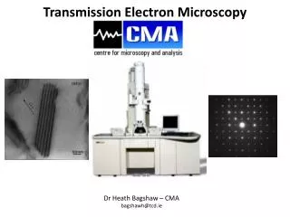
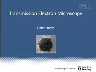
Transmission Electron Microscopy ZEISS 10A conventional transmission electron microscope (100,000 volts) • Configured for conventional imaging in the biological sciences and other simple specimens • Robust and simple to operate (in comparison) • Monostable switch controls hysteresis • Measured stability of magnification ±1% • Magnification range X100 to 200,000 • 3.4 Ångstrom resolution (point to point) • Microscope used for student instruction • Conventional 100 KV instruments are now ~$200,000
Transmission Electron Microscopy JEOL 2000-FX intermediate voltage (200,000 volt) scanning transmission research electron microscope (configured for both biological and physical sciences specimens) • magnification: X 50 to X 1,000,000 • 1.4 Ångstom resolution (LaB6 source) • backscattered and secondary electron detectors • Gatan Digi-PEELS Electron Energy Loss Spectrometer, software and off axis imaging camera • Kevex Quantum 10 mm2 X-ray detector (detects elements down to boron), with spatial resolution to as little as 20 nanometers (on thin sections) • IXRF X-ray analyzer with digital imaging capability, X-ray mapping, feature analysis and quantitative software. • Gatan Be double-tilt analytical holder for quantitative X-ray work • Gatan cryo-TEM specimen holder (to -150°C) • $700,000 as currently configured at current prices
JEOL 2010-F intermediate voltage (200,000 volt) field emission high resolution scanning transmission research electron microscope • Magnification: X 50 to X 1,000,000 • High resolution field emission gun (FEG) source producing coherent electron beam • Planned Gatan GIF and Electron Energy Loss Spectrometer (EELS) • Planned X-ray detector (detects elements to boron), spatial resolution to as little as 20 nm (on thin sections) • Specified res: ~1.2 Å • Other cool stuff • Planned acceptance date: Fall 2007
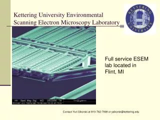
Scanning Electron Microscopy ZEISS DSM-960A scanning electron microscope – filament e- source • magnification: X 10 to X 300,000) • 30 Ångstrom resolution (approximate) • OXFORD Link Pentafet X-ray analyzer with IXRF software imaging capability, feature analysis and quantitative software. • digital images are usually acquired through a PC interface
Scanning Electron Microscopy JEOL JSM-880 high resolution SEM – LaB6 electron source • magnification: X 10 to X 300,000) • 15 Ångstrom resolution (LaB6 source) • backscattered electron detector, transmitted electron detector, electron channelling imaging • Double-tilt analytical holder with picoammeter for quantitative X-ray work • Kevex X-ray analyzer with IXRF software and digital imaging capability available • Equipped for x-ray feature analysis, mapping and quantitative analysis • Film support using sheet film or Polaroid is available, but most users opt for digital images • CDs and sleeves are provided per each session • $300,000 current value
Overview of a model TEM:Zeiss 10A The main components of a transmission electron microscope are: • Vacuum System • Electron Optics Column • Control and Display Consoles
Pump Tube to Cathode Head HV Pump Column Column Pump Tube to Double Projector Lens Specimen Airlock Valve Pump Tube to Specimen Chamber Plate Valve Pump Tube to Viewing Chamber Penning Gauge Plate Valve Water Flow Operated Switch By-Pass Valve Main Valve (V1) Manual Valve for Dessicator Magnetic Water Valve Dessicator Valve Baffle Pirani Gauge Diffusion Pump Pre-Vacuum Manifold High Voltage Cascade Ventilation Valve Rotary Pump 1 (Backs DP) Rotary Pump 2 (LV System) Vacuum System Schematic of Zeiss 10A Vacuum System • Low Vacuum Pumps • High Vacuum Pumps • Vacuum Gauges • Valves • Water Cooling
Electron Optics Column • Electron Beam Generation • Produces electrons and accelerates them toward specimen at HV • Electromagnetic Lenses • Condenser Lens (2) • Condenses electrons into nearly parallel beam (controls spot size, and brightness or intensity) • Objective Lens • Focuses beam that has passed through specimen (primary and scattered) and forms a magnified intermediate image. Focusing accomplished by varying current through lens • Intermediate Lens • Allows higher mags, more compact, shorter column, no distortion • Projector Lens • Magnifies a portion of the first image to form the final image • Stigmators • Used to adjust the shape of the beam (circular) • Caused by lens imperfections, aperture contamination, etc. • Gun Alignment • Deflector Coils
Electron Optics Column, cont. • Apertures • Spray or Fixed • Provide contrast • Movable • Depending on the aperture, can control brightness, resolution (balance diffraction versus spherical aberration), contrast, depth of field • Specimen Holder/Airlock • Viewing Area • Fluorescent Screen • Binoculars • Column should be vibrationally isolated
Biological Specimen Preparation Emphasizing ultramicrotomy
Overview of Biological Specimen Preparation Killing & Fixation - Death; Molecular stabilization Dehydration - Chemical removal of H2O Infiltration - Replace liquid phase with resin Embedding & Polymerization - Make solid, sectionable block Sectioning - Ultramicrotome, mount, stain
Technology of Sectioning • Ultramicrotome • Knife Selection • Specimen Preparation • Sectioning • Mounting Grids • Staining • A Few Sectioning Artifacts
Porter-Blum MT2B ultramicrotome by Sorvall (ca. mid-1960s-1980) • Simple belt device drives the microtome arm in MT2 • MT2B has adjustable duration and speed in the return stroke (much more complex) • Limited movement possible in the fluorescent bulb • Highly adjustable stage and specimen chuck, but all with spring locks rather than verniers making fine adj hard • Locks on microscope used rather than screws (also awkward) • Mechanical advance system
Reichert Ultracut Ultramicrotome • All adjustments are on viernier set screws facilitating fine adj • Lighting with above and sub-stage lamps • Mechanical advance with thick sectioning settings • Water bath controls • Fine control of speed and duration of cut and return cycle • Future models had innovations for serial sectioning
Knives • Razor blades did not last long • Took hours of honing to achieve translucence • Edge gone after one section • Glass knives • More durable and can be made easily • Inexpensive • Edge may last over 60 sections • Diamond knives • Expensive and fragile • Requires highly skilled user (no room for error) • Edge may last for years depending on user & cleanliness
Glass Knife Characteristics Good for ultrathin sectioning Good for thick sectioning Glass spur Edge defects(not suitable for sectioning) Wallner stress line sharpness durability
Caring for diamond knives: http://www.emsdiasum.com/Diatome/diamond_knives/manual.htm http://www.emsdiasum.com/Diatome/knife/images/
Estimating Thickness Interference reflection angle from Sjöstrand (1967) Sections of varying thicknesses as indicated by Sorvall interference colors (right). Image (left) is from http://www.jasonhostetter.com/pics/gallery/emu/bigpics/ultramicrotome.jpg
Physical Sciences Specimen Preparation - general techniques for materials sciences Direct lattice resolution in polydiacetylene single crystal showing (010)lattice planes spaced at 1.2 nm. http://www.ph.qmw.ac.uk/images/molwires.jpg
Physical Sciences Specimen Preparation - general techniques for materials sciences Direct lattice resolution in polydiacetylene single crystal showing (010)lattice planes spaced at 1.2 nm. http://www.ph.qmw.ac.uk/images/molwires.jpg
Technology of specimen preparation • Coarse preparation of samples: • Small objects (mounted on grids): • Strew • Spray • Cleave • Crush • Disc cutter (optionally mounted on grids) • Grinding device • Intermediate preparation: • Dimple grinder • Fine preparation: • Chemical polisher • Electropolisher • Ion thinning mill • PIMS: precision milling (using SEM on very small areas (1 X 1 μm2) • PIPS: precision ion polishing (at 4° angle) removes surface roughness with minimum surface damage • Beam blockers may be needed to mask epoxy or easily etched areas • Each technique has its own disadvantages and potential artifacts
Grid selection • Specialized grids include: • Bar grids • Mixed bar grids • Folding grids • Slot grids • Hexagonal grids • Mesh is designated in divisions per inch (50 – 1000) • Materials vary from copper and nickel to esoteric selections (Ti, Pt, Au, Ag etc.) based on various demands These are available from routine TEM suppliers – coated or not. Williams & Carter, 1996, Fig. 10-2
90° Wedge specimen • The 90°-wedge specimen: • Prethin to create 2-mm square of the multilayers on a Si substrate. • Scribe Si through surface layers, turn over, and cleave. • Inspect to make sure the cleavage is clean, giving a sharp 90° edge, reject if not. • Mount 90° corner over edge of hole in Cu slot grid and insert in TEM. • Note two different orientations are available from single cleavage operation. Williams & Carter, 1996, Fig. 10-17
Cross sectional views • Cross sectional views of reasonably thin sliceable materials: • Sheet sample is cut into slices and stacked with spacers placed to the outside • Sandwiched materials are mounted in slot and glued together for support • Material is observed in TEM Williams & Carter, 1996, Fig. 10-12
Sandwiching techniques • Cross sectional preparation technique for layered specimens: • Etching of a multilayer sample. • Etch away most of the sample, leaving a small etched plateau. • Mask a region < 50 nm across. • Etch away the majority of the surrounding plateau. • If this thin region is turned 90° and mounted in a specimen holder. • Interface is viewed parallel to electron beam. Williams & Carter, 1996, Fig. 10-18
Window polishing • Procedures for performing window polishing of conductive sheet materials: • A sheet of the metal1 cm2 is lacquered around the edges and made anode of an electrolytic cell. • Initial perforation usually occurs at the top of the sheet. • Lacquer is used to cover the initial perforation and sheet is rotated 180°. • Thinning continues to ensure that final thinning occurs near the center of the sheet. • If final edge is smooth rather than jagged it is probably too thick. Williams & Carter, 1996, Fig. 10-2
Lithographic masking • Lithographic techniques applied to thinning a multi-layer specimen: • Unthinned sample is shown with a grid of Si3N4 barrier layers evident. • Etching between barrier layers produces undercutting down to the implanted layer, producing uniform layer ~10 μm thick. • Further thinning with different solution produces large areas of uniformly thin material. • Si3N4 grid supports remaining unthinned regions. Williams & Carter, 1996, Fig. 10-19
Disc punch / drill Disc of 3 mm diameter is cut from raw “bulk” specimen Heating plate is provided for gluing specimens Rough polishing proceeds to a thickness of ~100 μm or so Rim provides a gripping area imparting structural rigidity to the specimen Pressure meter provides a guide to how cutting proceeds Samples from this step are often differentially ground in the center in a “dimple grinder”
Dimple grinder Grinding wheel provides thin center and durable rim Pressure, speed, and depth of grinding can be selected by controls Stop at several μm thickness Dimple grinding of 3 mm discs is usually preparative to another more precise method of thinning, such as ion milling, chemical or electropolishing.
Chemical polishing • Chemical polishing procedure: • This device is gravity fed. • Punched 3 mm specimen is suspended in meniscus of etchant. • Etchant flow is started. • Progress in etching specimen is monitored by illuminating glass tube. • Light in glass tube and etchant acts as a fiber optic source • Specimen transparency is viewed in mirror. • Unidirectional polishing in this design • Design could, if needed, be redesigned for bidirectional etching. Williams & Carter, 1996, Fig. 10-5
Gravity-fed & twin-jet electropolishing Gravity-fed one surface electropolisher (left), which uses reservoir as cathode. Twin-jet electropolisher uses specimen as conductor (above). Williams & Carter, 1996, Fig. 10-7
Electropolishing • Electropolishing curve showing the increase in current between the anode and the cathode as the applied voltage is increased. • Polishing occurs on the plateau, etching at low voltages, and pitting at high voltages. • Ideal conditions for obtaining a polished surface require the formation of a viscous film between the electrolyte and the specimen surface. Williams & Carter, 1996, Fig. 10-6
TEM sample preparation using the method of electrochemical polishing. Best results were obtained using 30% HNO3 in CH3OH at temperature of -200 C and a voltage of 15-20 V. This method was used because of the larger amounts of transparent area compared with ion beam milling. http://www.phys.rug.nl/mk/research/98/hrtem_localprobe.html
Ion mill schematic • Schematic diagram of an ion-beam thinning device: • Ar gas bleeds into the partial vacuum of ionization chamber • 6 keV potential creates beam of Ar ions on rotating specimen • Either one or both guns may be selected • Rotation speed and angle may be altered • Progress in thinning is viewed using a monocular microscope & back lighting. • Specimen may be cooled to LN2 temperatures. • Perforation is detected by penetration of ions through specimen. Williams & Carter, 1996, Fig. 10-8
Gatan Dual Ion Thinning Mill • General ion milling procedure: • Sample bombarded by an argon or iodine plasma. • Bombardment dislodges atoms from specimen surface. • Preparation is terminated when specimen is thin enough to see through or perforated. • Layers of 1 to several atoms of thickness are observed in TEM. • Can be adapted for en face thinning and for cross sectional views. Milling speed is controlled by:(1) specimen current, (2) plasma density (partial vacuum & gas concentration), (3) type of plasma (argon or iodine gas), (4) specimen angle, (5) milling temperature (LN2 dewars can be used), (6) ion guns (one or both) activated and (7) time. Intervention often needed:to adjust specimen current as specimen thinning proceeds. Laser cut-off device:is provided to terminate milling once a selected intensity of light passage is reached.
Gatan Dual Ion Thinning Mill Specimen port Microscope viewer Laser terminator Argon tank Mill controls Ion mill selector Vacuum meter Elapsed time Bias voltage Gun current Rotation Specimen current