Download
1 / 53
530 likes | 542 Vues
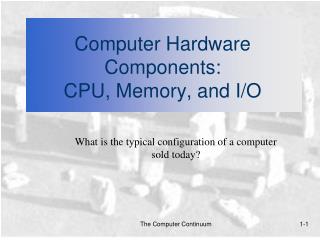
CPU with memory. Compiled by IITG. Basic Hardware Components of a computer. CPU (the brain, the thinking ) Memory ( active information) External Storage (mass knowledge) Input devices Output devices Communication devices.

E N D
CPU with memory Compiled by IITG
Basic Hardware Components of a computer • CPU (the brain, the thinking ) • Memory ( active information) • External Storage (mass knowledge) • Input devices • Output devices • Communication devices
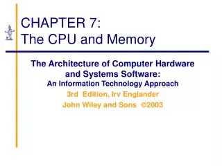
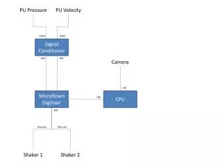
The central processing unit (CPU) of a computer is the main unit that dictates the rest of the computer organization and performs the bulk of data processing operations. • Central Processing Unit = “brain” • CPU communicate with other hardware components through data buses. Control Unit Arithmetic Logic Unit I/O Devices Main Memory Disk Input Output Registers Bus
Basic Hardware Components of a computer • CPU (brain, the thinking ) • Memory ( active information) • External Storage (mass knowledge) • Input devices • Output devices • Communication devices
CPU: 3 Major Components • ALU (arithmetic logic unit) • Performs calculations and comparisons (data changed) • CU (control unit): performs fetch/execute cycle • Functions: • Moves data to and from CPU registers and other hardware components (no change in data) • Accesses program instructions and issues commands to the ALU • Subparts: • Memory management unit: supervises fetching instructions and data • I/O Interface: sometimes combined with memory management unit as Bust Interface Unit • Registers • Example: Program counter(PC) or instruction pointer determines next instruction for execution Chapter 7 CPU and Memory
Central Processing Unit • The CPU is made up of three major parts: • Register set • ALU • Control units
CPU must have some working space to efficiently store intermediate values (instructions or data). • The registers are like built-in storage spaces in the processor. These space will hold the data and instructions copied from memory. • The registers are also wired (connected) with control unit and ALU. • The registers are part of the CPU. They are located inside the CPU, instead of in RAM, so data can be manipulated by the other two parts of the CPU. • Registers are high-speed memory. • Registers are limited, only a dozen in a CPU. • Registers are temporary memory. Once power is off, the data will be lost.
General Organization of Register set • There are only several registers in CPU. All the code and data get chances to be fed into proper registers as the program runs. • Program Counter (PC) keeps tracks of the address of the instruction currently being executed. (Where or which). • Instruction Register (IR) stores a copy of the instruction loaded from main memory. (What), closely tied to the control unit. • General purpose registers are the one we use most of the time. most instructions perform on these registers. Stores intermediate data during the execution of instructions; temporarily holds data taken from or about to be sent to memory. A storage register for regular operations. • AC Accumulator stores the result of a previous computation or a value communicated with the main memory. • Segment registers stores the positions of program segments. There are four or more segment registers: CS contains the segment of the current instruction (PC is the offset), SS contains the stack segment (SP is the offset), DS is the segment used by default for most data operations, ES is an extra segment register. • Indexes and pointers indexes and pointer and the offset part of and address. They have various uses but each register has a specific function. They some time used with a segment register to point to far address. • The EFLAGS register holds the state of the processor. It is modified by many instructions and is used for comparing some parameters, conditional loops and conditional jumps. Each bit holds the state of specific parameter of the last instruction.
Special roles are assigned to certain registers. i.e. the control logic is specially wired. • So, certain operations tend to (sometimes must) use certain registers, while most operations can use different general purpose registers freely.
instruction register • An instruction register is the part of a CPU's control unit that stores the instruction currently being executed or decoded. In simple processors each instruction to be executed is loaded into the instruction register which holds it while it is decoded, prepared and ultimately executed, which can take several steps. • More complicated processors use a pipeline of instruction registers where each stage of the pipeline does part of the decoding, preparation or execution and then passes it to the next stage for its step. Modern processors can even do some of the steps of out of order as decoding on several instructions is done in parallel. • Decoding the opcode in the instruction register includes determining the instruction, determining where its operands are in memory, retrieving the operands from memory, allocating processor resources to execute the command, etc.
Why not more registers? • The more space, the more convenient, right? • Sounds like yes, … but why not more registers? • It more registers, means more control units, more wires, more costly, more complicated … • Operations on registers generate heats. • The more complicated the CPU is, the more heats generated.
The Arithmetic/Logic Unit • The abbreviation of arithmetic logic unit , ALU contains the electronic circuitry that executes all arithmetic and logical operations to process data saved in register sets; • As its name implies, the arithmetic/logic unit can perform both arithmetic and logic operations. • four kinds of arithmetic operations, or mathematical calculations: addition, subtraction, multiplication, and division. • Logic operators usually are AND, OR, NOT and XOR at bits level, but at CPU level, LU supports comparison operations two. The unit can compare two bytes to determine if one is greater than, less than, equal to, or not equal to another. The control unit can then take action based on the result of the comparison. This is a very important capability.
Control Unit • Simply put, the control unit executes programs. • The control unit of the CPU contains circuitry that uses electrical signals to direct the entire CPU to execute instructions and transfer data. • The functions performed by the control unit vary greatly by the internal architecture of the CPU, since the control unit really implements the architecture. • On a regular processor that executes x86 instructions natively the control unit tyipcally performs a five step operation cycle in executing instructions: fetching, decoding, increment, managing execution of programs and then storing results. • On a x86 processor with a RISC core or other more advanced CPUs, the control unit has significantly more work to do. • Like an orchestra leader, the control unit does not execute program instructions; rather, it directs other parts of the system to do so. • The control unit must communicate with both the arithmetic/logic unit and registers, as well as memory. • Control unit supervises the transfer of information among the registers and instructs the ALU as to which operation to perform by generating control signals.
System Block Diagram Chapter 7 CPU and Memory
The Little Man Computer Chapter 7 CPU and Memory
Concept of Registers • Small, permanent storage locations within the CPU used for a particular purpose • Manipulated directly by the Control Unit • Wired for specificfunction • Size in bits or bytes (not MB like memory) • Can hold data, an address or an instruction • How many registers does the LMC have? Chapter 7 CPU and Memory
Registers • Use of Registers • Scratchpad for currently executing program • Holds data needed quickly or frequently • Stores information about status of CPU and currently executing program • Address of next program instruction • Signals from external devices • General Purpose Registers • User-visible registers • Hold intermediate results or data values, e.g., loop counters • Equivalent to LMC’s calculator • Typically several dozen in current CPUs Chapter 7 CPU and Memory
Special-Purpose Registers • Program Count Register (PC) • Also called instruction pointer • Instruction Register (IR) • Stores instruction fetched from memory • Memory Address Register (MAR) • Memory Data Register (MDR) • Status Registers • Status of CPU and currently executing program • Flags (one bit Boolean variable) to track condition like arithmetic carry and overflow, power failure, internal computer error Chapter 7 CPU and Memory
Register Operations • Stores values from other locations (registers and memory) • Addition and subtraction • Shift or rotate data • Test contents for conditions such as zero or positive Chapter 7 CPU and Memory
Operation of Memory • Each memory location has a unique address • Address from an instruction is copied to the MAR which finds the location in memory • CPU determines if it is a store or retrieval • Transfer takes place between the MDR and memory • MDR is a two way register Chapter 7 CPU and Memory
Data Address Relationship between MAR, MDR and Memory Chapter 7 CPU and Memory
MAR-MDR Example Chapter 7 CPU and Memory
Visual Analogy of Memory Chapter 7 CPU and Memory
Individual Memory Cell Chapter 7 CPU and Memory
Memory Capacity • Determined by two factors 1. Number of bits in the MAR • LMC = 100 (00 to 99) • 2K where K = width of the register in bits 2. Size of the address portion of the instruction • 4 bits allows 16 locations • 8 bits allows 256 locations • 32 bits allows 4,294,967,296 or 4 GB • Important for performance • Insufficient memory can cause a processor to work at 50% below performance Chapter 7 CPU and Memory
RAM: Random Access Memory • DRAM (Dynamic RAM) • Most common, cheap • Volatile: must be refreshed (recharged with power) 1000’s of times each second • SRAM (static RAM) • Faster than DRAM and more expensive than DRAM • Volatile • Frequently small amount used in cache memory for high-speed access used Chapter 7 CPU and Memory
ROM - Read Only Memory • Non-volatile memory to hold software that is not expected to change over the life of the system • Magnetic core memory • EEPROM • Electrically Erasable Programmable ROM • Slower and less flexible than Flash ROM • Flash ROM • Faster than disks but more expensive • Uses • BIOS: initial boot instructions and diagnostics • Digital cameras Chapter 7 CPU and Memory
Fetch-Execute Cycle • Two-cycle process because both instructions and data are in memory • Fetch • Decode or find instruction, load from memory into register and signal ALU • Execute • Performs operation that instruction requires • Move/transform data Chapter 7 CPU and Memory
LMC vs. CPUFetch and Execute Cycle Chapter 7 CPU and Memory
Load Fetch/Execute Cycle Chapter 7 CPU and Memory
Store Fetch/Execute Cycle Chapter 7 CPU and Memory
ADD Fetch/Execute Cycle Chapter 7 CPU and Memory
LMC Fetch/Execute SUBTRACT PC MAR MDR IR IR[addr] MAR A – MDR A PC + 1 PC IN PC MAR MDR IR IOR A PC + 1 PC OUT PC MAR MDR IR A IOR PC + 1 PC HALT PC MAR MDR IR BRANCH PC MAR MDR IR IR[addr] PC BRANCH on Condition PC MAR MDR IR If condition false: PC + 1 PC If condition true: IR[addr] PC Chapter 7 CPU and Memory
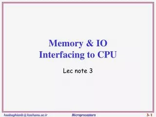
Bus • The physical connection that makes it possible to transfer data from one location in the computer system to another • Group of electrical conductors for carrying signals from one location to another • Line: each conductor in the bus • 4 kinds of signals • Data (alphanumeric, numerical, instructions) • Addresses • Control signals • Power (sometimes) Chapter 7 CPU and Memory
Bus • Connect CPU and Memory • I/O peripherals: on same bus as CPU/memory or separate bus • Physical packaging commonly called backplane • Also called system bus or external bus • Example of broadcast bus • Part of printed circuit board called motherboard that holds CPU and related components Chapter 7 CPU and Memory
Bus Characteristics • Protocol • Documented agreement for communication • Specification that spells out the meaning of each line and each signal on each line • Throughput, i.e., data transfer rate in bits per second • Data width in bits carried simultaneously Chapter 7 CPU and Memory
Point-to-point vs. Multipoint Plug-in device Broadcast bus Example: Ethernet Shared among multiple devices Chapter 7 CPU and Memory
Motherboard • Printed circuit board that holds CPU and related components including backplane Chapter 7 CPU and Memory
Typical PC Interconnections Bus interface bridges connect different bus types Chapter 7 CPU and Memory
PCI Bus Connections Chapter 7 CPU and Memory
Instructions • Instruction • Direction given to a computer • Causes electrical signals to be sent through specific circuits for processing • Instruction set • Design defines functions performed by the processor • Differentiates computer architecture by the • Number of instructions • Complexity of operations performed by individual instructions • Data types supported • Format (layout, fixed vs. variable length) • Use of registers • Addressing (size, modes) Chapter 7 CPU and Memory
Source OPERAND Result OPERAND OPCODE InstructionElements • OPCODE: task • Source OPERAND(s) • Result OPERAND • Location of data (register, memory) • Explicit: included in instruction • Implicit: default assumed Addresses Chapter 7 CPU and Memory
Instruction Format • Machine-specific template that specifies • Length of the op code • Number of operands • Length of operands Simple 32-bit Instruction Format Chapter 7 CPU and Memory
Instruction Formats: CISC Chapter 7 CPU and Memory
Instruction Formats: RISC Chapter 7 CPU and Memory
Instruction Types • Data Transfer (load, store) • Most common, greatest flexibility • Involve memory and registers • What’s a word? 16? 32? 64 bits? • Arithmetic • Operators + - / * ^ • Integers and floating point • Logical or Boolean • Relational operators: > < = • Boolean operators AND, OR, XOR, NOR, and NOT • Single operand manipulation instructions • Negating, decrementing, incrementing Chapter 7 CPU and Memory
More Instruction Types • Bit manipulation instructions • Flags to test for conditions • Shift and rotate • Program control • Stack instructions • Multiple data instructions • I/O and machine control Chapter 7 CPU and Memory
Register Shifts and Rotates Chapter 7 CPU and Memory
Program Control Instructions • Program control • Jump and branch • Subroutine call and return Chapter 7 CPU and Memory
Stack Instructions • Stack instructions • LIFO method for organizing information • Items removed in the reverse order from that in which they are added Push Pop Chapter 7 CPU and Memory