Download
1 / 24
1.67k likes | 3.15k Vues
Engineering Graphics- Basics. By Mr.B.Ramesh, M.E ., (Ph.D.), Research Scholar, CEG, Anna University, Chennai. Associate Professor, Department of Mechanical Engineering, St. Joseph’s College of Engineering, Jeppiaar Trust, Chennai-119. DRAWINGS: ( A Graphical Representation).

E N D
Engineering Graphics- Basics By Mr.B.Ramesh, M.E., (Ph.D.), Research Scholar, CEG, Anna University, Chennai. Associate Professor, Department of Mechanical Engineering, St. Joseph’s College of Engineering, Jeppiaar Trust, Chennai-119
DRAWINGS: ( A Graphical Representation) The Fact about: If compared with Verbal or Written Description, Drawings offer far better idea about the Shape, Size & Appearance of any object or situation or location, that too in quite a less time. Hence it has become the Best Media of Communication not only in Engineering but in almost all Fields.
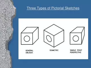
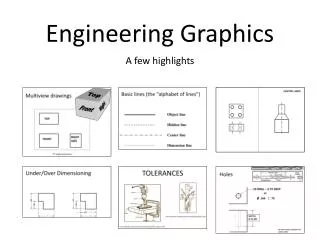
Drawings (Some Types) Portraits ( human faces, expressions etc.) Botanical Drawings ( plants, flowers etc.) Nature Drawings ( landscape, scenery etc.) Geographical Drawings ( maps etc.) Zoological Drawings (creatures, animals etc.) Engineering Drawings, (projections.) Machine component Drawings Building Related Drawings. Orthographic Projections (Fv,Tv & Sv.-Mech.Engg terms) (Plan, Elevation- Civil Engg.terms) (Working Drawings 2-D type) Isometric ( Mech.Engg.Term.) or Perspective(Civil Engg.Term) (Actual Object Drawing 3-D)
Basics: ♣ Drawing: 2D or 3D views of an object without the purpose of manufacturing it. It is done manually or with the aid of a computer. ♣ Engineering Drawing: 2D or 3D views of an object with the purpose of manufacturing it. It is done manually. ♥ Note: In 2D view ( Orthographic projection ), one view is not enough to get all the details of the object. So it is necessary to draw the front view, top view, bottom view, right side view and left side view. ♣ Engineering Graphics: 2D or 3D views of an object with the purpose of manufacturing it. It is done with the aid of a computer. ♣ Drawing sheet: Drawing paper is in the form of sheet or roll. Trimmed drawing paper is called as drawing sheet. The designations of drawing sheet are : A0, A1, A2, A3 and A4.
♣ Compass: ♥ Bow compass is used for drawing small circles up to 30 mmdiameter. In this, the inclined cut of the lead is turned inside as shown in the figure. Note: Pro-circle can also be used for drawing small circles up to 30 mm diameter. ♥ Large compass is used to draw circles from 30 mm to 120 mm diameter. In this the inclined cut of the lead is turned outside as shown in the figure. ♥ Up to 120 mm diameter, circles can be drawn with the legs of the compass kept straight.
♥ For drawing larger circles both the legs must be bent at their knee joints, so that they are perpendicular to the surface of the paper. For drawing circles of 120 to 300 mm diameter both the needle point leg and the pencil leg should be bent at the knuckle joints so as to be perpendicular to the surface of the paper. ♥ For drawing larger circles of more than 300 mm diameter, lengthening bar attachment is used. For this, the lower part of the pencil leg is detached and lengthening bar is inserted in its place. The detached part is then fitted at the end of the lengthening bar.
♥ In any compass the pencil / lead should project 1 mm less than the needle point as shown in the figure. ♥ While taking measurements using compass / divider, place the compass / divider such that it is inclined by 450 to the surface of the paper. ♣ The bottom horizontal edges of drawing board, pading sheet and drawing sheet should coincide as shown in the figure. The right vertical edges of drawing board, pading sheet and drawing sheet should coincide as shown in the figure. Use double sided tape instead of cello tape.
♣ How to fix the mini drafter on the drawing board? ♥ A miniature of drafting machine is mini drafter. ♥ The mini drafter should be positioned on the top left hand side of the drawing board such that the scales ( horizontal and vertical ) of the mini drafter covers the drawing space fully. Note : The longer scale of the mini drafter should be horizontal and called as horizontal scale. The shorter scale of the mini drafter should be vertical and called as vertical scale. ♥ Loose the adjusting knob and clamping knob. ♥ The horizontal scale of the drafter should be aligned with the top horizontal edge of the drawing sheet. Also, make the mark in the drafter to coincide with 00 in the protractor. ♥ Holding the horizontal scale of the drafter in this position, tight the adjusting knob first and then tight the clamping knob. ♥ Now the mini drafter can be used to draw horizontal and vertical lines. After drawing inclined lines, make the horizontal scale (or vertical scale) of the drafter to align with any previous horizontal line ( or vertical line) and tight the adjusting knob. ♣ How to take angles using mini drafter ? ♥ For taking angles from the vertical line, rotate the vertical scale of the mini-drafter clockwise or anti clockwise to the required angle and draw the inclined line using vertical scale. ♥ For taking angles from the horizontal line, rotate the horizontal scale of the mini-drafter clockwise or anti clockwise to the required angle and draw the inclined line using horizontal scale.
♣ Layout of A2 size drawing sheet for assignment work: ♥ Title block is necessary and fold the drawing sheet(six fold) as given below. ♥ “ALL DIMENSIONS ARE IN mm” should be written above the title block. ♥ If any different scale is used write that beneath the corresponding problem.
♣ Layout of A3 size drawing sheet for Unit and Model exams: ♥ Title block is not necessary. Write your roll no., branch and section withpen at the bottom right end of the drawing sheet. For that take size 7 mm. Fold the drawing sheet in the middle (one fold) such that your roll no. is visible. ♥ Write “ALL DIMENSIONS ARE IN mm” and Scale: 1 : 1 above your roll no. For that take size 5 mm. If any different scale is used write that beneath the corresponding problem.
♣ Layout of A3 size drawing sheet for university exams: ♥ 5 sheets will be given. Title block is not necessary. Write your registration no. etc., only in the paper provided in front and not in the drawing sheets. It is not necessary to fold the drawing sheets. ♥ Write “ALL DIMENSIONS ARE IN mm” and Scale: 1 : 1 at the bottom right end of all the sheets. For that take size 5 mm. If any different scale is used write that beneath the corresponding problem. ♣ The left side 20 mm is given for filing and binding purposes. Border line is a very thick line which serves as a frame for the drawing sheet.
♣ Title block for assignment work: ♥ For title of the drawing take size 7 mm. For others take size 5 mm. ♥ If more than one drawing sheet is used for a particular TITLE OF THE DRAWING, sheet no. is n/p, where n is the sheet no. and p is the total no. of sheets. i.e. if for projections of lines 2 sheets (not pages) are used, then sheet no. is 1/2 and 2/2. ♥ The symbol for first angle projection is drawn. ♥ Write your name, roll no., branch and section with pen.
♣ How to fold the A2 size drawing sheets for assignment work? ♥ Mark 190 mm from the right edge of the drawing sheet. Mark 186 mm from the previous mark. Mark 20 mm from the left edge of the drawing sheet. ♥ Mark 297 mm from the bottom edge of the drawing sheet on the reverse side. ♥ Coincide the first fold with third fold to get second fold. Coincide the third fold with the border line which is 20 mm to the right of left edge of drawing sheet to get fourth fold. Fifth and sixth folds are back folds. ♥ All larger size drawing sheets i.e. A0, A1, A2 and A3 are folded to A4 size sheet.
♣ Drawing pencils are made in many grades. The grade HB denotes medium soft. The grades H, 2H, 3H …9H denotes the degree of hardness (of graphite lead) in an increasing order. So, the darkness of the line made by the pencil goes on decreasing. Similarly, grades B, 2B, 3B…7B denotes the degree of softness (of graphite lead) in an increasing order. So, the darkness of the line made by the pencil goes on increasing. ♣ The grade of the pencil / lead is decided by the amount of graphite mixed with clay. That is, more amount of graphite mixed with less amount of clay increases the softness of the pencil / lead and thereby increases the darkness of the line and vice versa. ♣ For better understanding of any object, it is essential to differentiate the various types of lines. HB pencil ( Very thick line ) → Border, Title block, Arrow head and Free hand sketch. H pencil ( Thick line) → Final projections, Hidden edges, Lettering (Alphabets & Numbers) 2H pencil ( Thin line ) →Reference lines, Projectors, Construction lines, Dimension lines, Extension lines, Leader lines, Section lines and Centre lines(axis). Use micro tip pencil to get neat drawings. Use micro tip pencil (0.5 mm lead of grade H) to replace H and 2H wooden pencils. While using the above micro tip pencil care should be taken to differentiate thick and thin lines. For very thick line use micro tip pencil (0.5 mm lead of grade HB). Note: Micro tip pencils, otherwise known as clutch pencils or mechanical pencils, with 0.5 mm thick leads of different grades viz. HB, H and 2H are preferred than wooden pencils, as they need no sharpening.
♣ How to draw axis? Axis should be drawn as a long-dashed dotted thin line as shown below. Axis should extend beyond the boundary of a figure by a short distance. ♣ Scale: Drawing size : Actual size 1 : 1 → Full size scale 2 : 1, 3 : 1, …100 : 1, … → Enlargement scale 1 : 2, 1 : 3, …1 : 100, … → Reduction scale Note : ♥ Whatever the scale may be, the angle remains the same. ♥ Whatever the scale may be, only the actual size should be mentioned in the drawing while dimensioning. ♥ If you use enlargement scale or reduction scale mention that beneath the corresponding problem. Eg. SCALE : 2 : 1 ♣ Usage of mini drafter is a must. ♣ For drawing arrow heads remember the ratio 3 : 1. It dosen’t mean 3 mm : 1 mm. Shade the closed arrow head with HB pencil. Always draw the arrow heads proportionate to the space available between the extension lines.
Lettering: ♥ In an engineering drawing, it is necessary that the drawing of a component should accompany with some written details, to convey the technical information such as name of the company, part details, information regarding the component, manufacturing process, scale etc. Representing the above particulars and sizes of a component on an engineering drawing is known as Lettering. Note: Lettering includes both alphabets and numbers. ♥ Lettering should be done with free hand and not with drawing instruments. ♥ Both vertical and inclined letters are in use. ♥ In an engineering drawing all the letters must be in upper-case and lower-case letters are used for abbreviations. ♥ The scale (other than full size scale) and required answers should be written (with H pencil) beneath the corresponding problem taking the size of letters (use vertical capital letters) as 5 mm. ♥ Alphabets and numbers should be obtained in single stroke of the pencil.
♣ The following figures illustrates the Aligned system of dimensioning:
THIS QUADRANT PATTERN, IF OBSERVED ALONG X-Y LINE ( IN RED ARROW DIRECTION) WILL EXACTLY APPEAR AS SHOWN ON RIGHT SIDE AND HENCE, IT IS FURTHER USED TO UNDERSTAND ILLUSTRATION PROPERLLY. 2nd Quadrant VP 1ST Quad. 2nd Quad. F.V. 1st Quadrant Y Observer HP X Y X 3rdQuadrant Observer 4th Quad. 3rd Quad. 4th Quadrant
FIRST ANGLE PROJECTION FOR T.V. PP VP FOR S.V. FOR F.V. FV LSV Y X TV HP IN THIS METHOD, THE OBJECT IS ASSUMED TO BE SITUATED IN FIRST QUADRANT MEANS ABOVE HP & INFRONT OF VP. P.P. V.P. S.V. F.V. OBJECT IS INBETWEEN OBSERVER & PLANE. OBJECT ACTUAL PATTERN OF PLANES & VIEWS IN FIRST ANGLE METHOD OF PROJECTIONS
FOR T.V. FOR S.V. FOR F.V. THIRD ANGLE PROJECTION IN THIS METHOD, THE OBJECT IS ASSUMED TO BE SITUATED IN THIRD QUADRANT ( BELOW HP & BEHIND OF VP. ) PLANES BEING TRANSPERENT AND INBETWEEN OBSERVER & OBJECT. P.P. V.P. OBJECT TV X Y S.V. F.V. FV LSV ACTUAL PATTERN OF PLANES & VIEWS OF THIRD ANGLE PROJECTIONS
TV FV Y X Y X FV TV L G Methods of Drawing Orthographic Projections Third Angle Projections Method Here views are drawn by placing object in 3rd Quadrant. ( Tv above X-y, Fv below X-y) First Angle Projections Method Here views are drawn by placing object in 1st Quadrant ( Fv above X-y, Tv below X-y ) SYMBOLIC PRESENTATION OF BOTH METHODS WITH AN OBJECT STANDING ON HP ( GROUND) ON IT’S BASE. NOTE:- HP term is used in 1st Angle method & For the same Ground term is used in 3rd Angle method of projections