Download

1 / 43
450 likes | 669 Vues
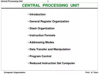
CENTRAL PROCESSING UNIT. Introduction General Register Organization Stack Organization Instruction Formats Addressing Modes Data Transfer and Manipulation Program Control Reduced Instruction Set Computer. Introduction. MAJOR COMPONENTS OF CPU. Storage Components

E N D
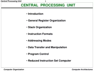
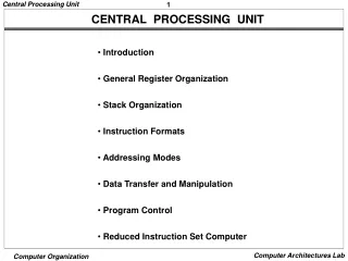
CENTRAL PROCESSING UNIT • Introduction • General Register Organization • Stack Organization • Instruction Formats • Addressing Modes • Data Transfer and Manipulation • Program Control • Reduced Instruction Set Computer
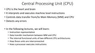
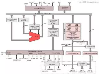
Introduction MAJOR COMPONENTS OF CPU Storage Components Registers Flags Execution(Processing) Components Arithmetic Logic Unit(ALU) Arithmetic calculations, Logical computations, Shifts/Rotates Transfer Components Bus Control Components Control Unit Register File ALU Control Unit
General Register Organization Input Clock R1 R2 R3 R4 R5 R6 R7 Load (7 lines) } { MUX MUX SELB SELA 3 x 8 A bus B bus decoder SELD ALU OPR Output GENERAL REGISTER ORGANIZATION
Control 3 3 3 5 SELA SELB SELD OPR OPERATION OF CONTROL UNIT The control unit Directs the information flow through ALU by - Selecting various Components in the system - Selecting the Function of ALU Example: R1 <- R2 + R3 [1] MUX A selector (SELA): BUS A R2 [2] MUX B selector (SELB): BUS B R3 [3] ALU operation selector (OPR): ALU to ADD [4] Decoder destination selector (SELD): R1 Out Bus Control Word Encoding of register selection fields • Binary • Code SELA SELB SELD • 000 Input Input None • 001 R1 R1 R1 • 010 R2 R2 R2 • 011 R3 R3 R3 • 100 R4 R4 R4 • 101 R5 R5 R5 • 110 R6 R6 R6 • 111 R7 R7 R7
Control ALU CONTROL Encoding of ALU operations OPR Select Operation Symbol 00000 Transfer A TSFA 00001 Increment A INCA 00010 ADD A + B ADD 00101 Subtract A - B SUB 00110 Decrement A DECA 01000 AND A and B AND 01010 OR A and B OR 01100 XOR A and B XOR 01110 Complement A COMA 10000 Shift right A SHRA 11000 Shift left A SHLA Examples of ALU Microoperations Symbolic Designation Microoperation SELA SELB SELD OPR Control Word • R1 R2 - R3 R2 R3 R1 SUB 010 011 001 00101 • R4 R4 R5 R4 R5 R4 OR 100 101 100 01010 • R6 R6 + 1 R6 - R6 INCA 110 000 110 00001 • R7 R1 R1 - R7 TSFA 001 000 111 00000 • Output R2 R2 - None TSFA 010 000 000 00000 • Output Input Input - None TSFA 000 000 000 00000 • R4 shl R4 R4 - R4 SHLA 100 000 100 11000 • R5 0 R5 R5 R5 XOR 101 101 101 01100
Stack Organization REGISTER STACK ORGANIZATION Stack - Very useful feature for nested subroutines, nested loops control - Also efficient for arithmetic expression evaluation - Storage which can be accessed in LIFO - Pointer: SP - Only PUSH and POP operations are applicable stack Address 63 Register Stack Flags FULL EMPTY Stack pointer 4 SP C 3 B 2 A 1 Push, Pop operations 0 DR /* Initially, SP = 0, EMPTY = 1, FULL = 0 */ PUSH POP • SP SP + 1 DR M[SP] • M[SP] DR SP SP - 1 • If (SP = 0) then (FULL 1) If (SP = 0) then (EMPTY 1) • EMPTY 0 FULL 0
Stack Organization MEMORY STACK ORGANIZATION 1000 Program Memory with Program, Data, and Stack Segments PC (instructions) Data AR (operands) 3000 SP stack 3997 3998 3999 4000 4001 • - A portion of memory is used as a stack with a • processor register as a stack pointer • - PUSH: SP SP - 1 • M[SP] DR • - POP: DR M[SP] • SP SP + 1 • - Most computers do not provide hardware to check • stack overflow (full stack) or underflow(empty stack) DR
Stack Organization REVERSE POLISH NOTATION Arithmetic Expressions: A + B A + B Infix notation + A B Prefix or Polish notation A B + Postfix or reverse Polish notation - The reverse Polish notation is very suitable for stack manipulation Evaluation of Arithmetic Expressions Any arithmetic expression can be expressed in parenthesis-free Polish notation, including reverse Polish notation (3 * 4) + (5 * 6) 3 4 * 5 6 * + 6 4 5 5 30 12 12 42 3 3 12 12 3 * 5 * + 4 6
Instruction Format INSTRUCTION FORMAT Instruction Fields OP-code field - specifies the operation to be performed Address field - designates memory address(es) or a processor register(s) Mode field - specifies the way the operand or the effective address is determined The number of address fields in the instruction format depends on the internal organization of CPU - The three most common CPU organizations: • Single accumulator organization: • ADD X /* AC AC + M[X] */ • General register organization: • ADD R1, R2, R3 /* R1 R2 + R3 */ • ADD R1, R2 /* R1 R1 + R2 */ • MOV R1, R2 /* R1 R2 */ • ADD R1, X /* R1 R1 + M[X] */ • Stack organization: • PUSH X /* TOS M[X] */ • ADD
Instruction Format THREE, AND TWO-ADDRESS INSTRUCTIONS Three-Address Instructions Program to evaluate X = (A + B) * (C + D) : ADD R1, A, B /* R1 M[A] + M[B] */ ADD R2, C, D /* R2 M[C] + M[D] */ MUL X, R1, R2 /* M[X] R1 * R2 */ - Results in short programs - Instruction becomes long (many bits) Two-Address Instructions Program to evaluate X = (A + B) * (C + D) : MOV R1, A /* R1 M[A] */ ADD R1, B /* R1 R1 + M[A] */ MOV R2, C /* R2 M[C] */ ADD R2, D /* R2 R2 + M[D] */ MUL R1, R2 /* R1 R1 * R2 */ MOV X, R1 /* M[X] R1 */
Instruction Format ONE, AND ZERO-ADDRESS INSTRUCTIONS One-Address Instructions - Use an implied AC register for all data manipulation - Program to evaluate X = (A + B) * (C + D) : LOAD A /* AC M[A] */ ADD B /* AC AC + M[B] */ STORE T /* M[T] AC */ LOAD C /* AC M[C] */ ADD D /* AC AC + M[D] */ MUL T /* AC AC * M[T] */ STORE X /* M[X] AC */ Zero-Address Instructions - Can be found in a stack-organized computer - Program to evaluate X = (A + B) * (C + D) : PUSH A /* TOS A */ PUSH B /* TOS B */ ADD /* TOS (A + B) */ PUSH C /* TOS C */ PUSH D /* TOS D */ ADD /* TOS (C + D) */ MUL /* TOS (C + D) * (A + B) */ POP X /* M[X] TOS */
Addressing Modes ADDRESSING MODES Addressing Modes * Specifies a rule for interpreting or modifying the address field of the instruction (before the operand is actually referenced) * Variety of addressing modes - to give programming flexibility to the user - to use the bits in the address field of the instruction efficiently
Addressing Modes TYPES OF ADDRESSING MODES Implied Mode Address of the operands are specified implicitly in the definition of the instruction - No need to specify address in the instruction - EA = AC, or EA = Stack[SP] Immediate Mode Instead of specifying the address of the operand, operand itself is specified - No need to specify address in the instruction - However, operand itself needs to be specified - Sometimes, require more bits than the address - Fast to acquire an operand Register Mode Address specified in the instruction is the register address - Designated operand need to be in a register - Shorter address than the memory address - Saving address field in the instruction - Faster to acquire an operand than the memory addressing - EA = IR(R) (IR(R): Register field of IR)
Addressing Modes TYPES OF ADDRESSING MODES Register Indirect Mode Instruction specifies a register which contains the memory address of the operand - Saving instruction bits since register address is shorter than the memory address - Slower to acquire an operand than both the register addressing or memory addressing - EA = [IR(R)] ([x]: Content of x) Register used in Register Indirect Mode may have Autoincrement or Autodecrement features - When the address in the register is used to access memory, the value in the register is incremented or decremented by 1 automatically Direct Address Mode Instruction specifies the memory address which can be used directly to the physical memory - Faster than the other memory addressing modes - Too many bits are needed to specify the address for a large physical memory space - EA = IR(addr) (IR(addr): address field of IR)
Addressing Modes TYPES OF ADDRESSING MODES Indirect Addressing Mode The address field of an instruction specifies the address of a memory location that contains the address of the operand - When the abbreviated address is used large physical memory can be addressed with a relatively small number of bits - Slow to acquire an operand because of an additional memory access - EA = M[IR(address)] Relative Addressing Modes The Address fields of an instruction specifies the part of the address (abbreviated address) which can be used along with a designated register to calculate the address of the operand - Address field of the instruction is short - Large physical memory can be accessed with a small number of address bits - EA = f(IR(address), R), R is sometimes implied 3 different Relative Addressing Modes depending on R; * PC Relative Addressing Mode(R = PC) - EA = PC + IR(address) * Indexed Addressing Mode(R = IX, where IX: Index Register) - EA = IX + IR(address) * Base Register Addressing Mode(R = BAR, where BAR: Base Address Register) - EA = BAR + IR(address)
Addressing Modes ADDRESSING MODES - EXAMPLES - Address Memory 200 Load to AC Mode Address = 500 PC = 200 201 202 Next instruction R1 = 400 399 450 XR = 100 400 700 AC 500 800 600 900 702 325 Addressing Mode Effective Address Content of AC • Direct address 500 /* AC (500) */ 800 • Immediate operand - /* AC 500 */ 500 • Indirect address 800 /* AC ((500)) */ 300 • Relative address 702 /* AC (PC+500) */ 325 • Indexed address 600 /* AC (RX+500) */ 900 • Register - /* AC R1 */ 400 • Register indirect 400 /* AC (R1) */ 700 • Autoincrement 400 /* AC (R1)+ */ 700 • Autodecrement 399 /* AC -(R) */ 450 800 300
Data Transfer and Manipulation DATA TRANSFER INSTRUCTIONS Typical Data Transfer Instructions Name Mnemonic Load LD Store ST Move MOV Exchange XCH Input IN Output OUT Push PUSH Pop POP Data Transfer Instructions with Different Addressing Modes Assembly Convention Mode Register Transfer Direct address LD ADR AC M[ADR] Indirect address LD @ADR AC M[M[ADR]] Relative address LD $ADR AC M[PC + ADR] Immediate operand LD #NBR AC NBR Index addressing LD ADR(X) AC M[ADR + XR] Register LD R1 AC R1 Register indirect LD (R1) AC M[R1] Autoincrement LD (R1)+ AC M[R1], R1 R1 + 1 Autodecrement LD -(R1) R1 R1 - 1, AC M[R1]
Data Transfer and Manipulation DATA MANIPULATION INSTRUCTIONS Arithmetic instructions Logical and bit manipulation instructions Shift instructions Three Basic Types: Arithmetic Instructions Name Mnemonic Increment INC Decrement DEC Add ADD Subtract SUB Multiply MUL Divide DIV Add with Carry ADDC Subtract with Borrow SUBB Negate(2’s Complement) NEG Shift Instructions Logical and Bit Manipulation Instructions Name Mnemonic Name Mnemonic Logical shift right SHR Logical shift left SHL Arithmetic shift right SHRA Arithmetic shift left SHLA Rotate right ROR Rotate left ROL Rotate right thru carry RORC Rotate left thru carry ROLC Clear CLR Complement COM AND AND OR OR Exclusive-OR XOR Clear carry CLRC Set carry SETC Complement carry COMC Enable interrupt EI Disable interrupt DI
Program Control PROGRAM CONTROL INSTRUCTIONS +1 In-Line Sequencing (Next instruction is fetched from the next adjacent location in the memory) Address from other source; Current Instruction, Stack, etc Branch, Conditional Branch, Subroutine, etc PC Program Control Instructions Name Mnemonic Branch BR Jump JMP Skip SKP Call CALL Return RTN Compare(by - ) CMP Test(by AND) TST * CMP and TST instructions do not retain their results of operations(- and AND, respectively). They only set or clear certain Flags. Status Flag Circuit A B 8 8 c7 8-bit ALU c8 F7 - F0 V Z S C F7 8 Check for zero output F
Program Control CONDITIONAL BRANCH INSTRUCTIONS Mnemonic Branch condition Tested condition BZ Branch if zero Z = 1 BNZ Branch if not zero Z = 0 BC Branch if carry C = 1 BNC Branch if no carry C = 0 BP Branch if plus S = 0 BM Branch if minus S = 1 BV Branch if overflow V = 1 BNV Branch if no overflow V = 0 Unsigned compare conditions (A - B) BHI Branch if higher A > B BHE Branch if higher or equal A B BLO Branch if lower A < B BLOE Branch if lower or equal A B BE Branch if equal A = B BNE Branch if not equal A B Signed compare conditions (A - B) BGT Branch if greater than A > B BGE Branch if greater or equal A B BLT Branch if less than A < B BLE Branch if less or equal A B BE Branch if equal A = B BNE Branch if not equal A B
Program Control SUBROUTINE CALL AND RETURN Call subroutine Jump to subroutine Branch to subroutine Branch and save return address SUBROUTINE CALL Two Most Important Operations are Implied; * Branch to the beginning of the Subroutine - Same as the Branch or Conditional Branch * Save the Return Address to get the address of the location in the Calling Program upon exit from the Subroutine - Locations for storing Return Address CALL SP SP - 1 M[SP] PC PC EA RTN PC M[SP] SP SP + 1 • Fixed Location in the subroutine(Memory) • Fixed Location in memory • In a processor Register • In a memory stack • - most efficient way
Program Control PROGRAM INTERRUPT Types of Interrupts External interrupts External Interrupts initiated from the outside of CPU and Memory - I/O Device -> Data transfer request or Data transfer complete - Timing Device -> Timeout - Power Failure - Operator Internal interrupts (traps) Internal Interrupts are caused by the currently running program - Register, Stack Overflow - Divide by zero - OP-code Violation - Protection Violation Software Interrupts Both External and Internal Interrupts are initiated by the computer HW. Software Interrupts are initiated by the executing an instruction. - Supervisor Call -> Switching from a user mode to the supervisor mode -> Allows to execute a certain class of operations which are not allowed in the user mode
Program Control INTERRUPT PROCEDURE Interrupt Procedure and Subroutine Call • - The interrupt is usually initiated by an internal or • an external signal rather than from the execution of • an instruction (except for the software interrupt) • - The address of the interrupt service program is • determined by the hardware rather than from the • address field of an instruction • - An interrupt procedure usually stores all the • information necessary to define the state of CPU • rather than storing only the PC. • The state of the CPU is determined from; • Content of the PC • Content of all processor registers • Content of status bits • Many ways of saving the CPU state • depending on the CPU architectures
RISC RISC: REDUCED INSTRUCTION SET COMPUTERS Historical Background IBM System/360, 1964 - The real beginning of modern computer architecture - Distinction between Architecture and Implementation - Architecture: The abstract structure of a computer seen by an assembly-language programmer -program Compiler High-Level Language Instruction Set Hardware Architecture Implementation Continuing growth in semiconductor memory and microprogramming -> A much richer and complicated instruction sets => CISC(Complex Instruction Set Computer) - Arguments advanced at that time • Richer instruction sets would simplify compilers • Richer instruction sets would alleviate the software crisis • - move as much functions to the hardware as possible • - close Semantic Gap between machine language • and the high-level language • Richer instruction sets would improve architecture quality
RISC ARCHITECTURE DESIGN PRINCIPLES - IN 70’s - • * Large microprograms would add little or nothing • to the cost of the machine • <- Rapid growth of memory technology • -> Large General Purpose Instruction Set • * Microprogram is much faster than the machine instructions • <- Microprogram memory is much faster than main memory • -> Moving the software functions into • Microprogram for the high performance machines • * Execution speed is proportional to the program size • -> Architectural techniques that led to small program • -> High performance instruction set • * Number of registers in CPU has limitations • -> Very costly • -> Difficult to utilize them efficiently
RISC COMPARISONS OF EXECUTION MODELS A B + C Data: 32-bit Register-to-register 8 4 16 Load rB B Load C rC Add rA rB rC Store rA A I = 104b; D = 96b; M = 200b Memory-to-register 8 16 Load B Add C A Store I = 72b; D = 96b; M = 168b Memory-to-memory 8 16 16 16 B C A Add I = 56b; D = 96b; M = 152b
RISC FOUR MODERN ARCHITECTURES IN 70’s Intel DEC Xerox IBM 370/168 VAX-11/780 Dorado iAPX-432 Year 1973 1978 1978 1982 # of instrs. 208 303 270 222 Control mem. size 420 Kb 480 Kb 136 Kb 420 Kb Instr. size (bits) 16-48 16-456 8-24 6-321 Technology ECL MSI TTL MSI ECL MSI NMOS VLSI Execution model reg-mem reg-mem stack stack mem-mem mem-mem mem-mem reg-reg reg-reg Cache size 64 Kb 64 Kb 64 Kb 64 Kb Changes in the Implementation World in 70’s * Main Memory is no longer 10 times slower than Microprogram memory -> microprogram rather slows down the speed * Caches had been invented -> Further improvement on the Main Memory speed * Compilers were subsetting architectures
RISC CRITICISM ON COMPLEX INSTRUCTION SET COMPUTERS Complex Instruction Set Computers - CISC High Performance General Purpose Instructions - Complex Instruction -> Format, Length, Addressing Modes -> Complicated instruction cycle control due to the complex decoding HW and decoding process - Multiple memory cycle instructions -> Operations on memory data -> Multiple memory accesses/instruction - Microprogrammed control is necessity -> Microprogram control storage takes substantial portion of CPU chip area -> Semantic Gap is large between machine instruction and microinstruction - General purpose instruction set includes all the features required by individually different applications -> When any one application is running, all the features required by the other applications are extra burden to the application
RISC PHYLOSOPHY OF RISC Reduce the semantic gap between machine instruction and microinstruction 1-Cycle instruction Most of the instructions complete their execution in 1 CPU clock cycle - like a microoperation * Functions of the instruction (contrast to CISC) - Very simple functions - Very simple instruction format - Similar to microinstructions => No need for microprogrammed control * Register-Register Instructions - Avoid memory reference instructions except Load and Store instructions - Most of the operands can be found in the registers instead of main memory => Shorter instructions => Uniform instruction cycle => Requirement of large number of registers * Employ instruction pipeline
RISC ARCHITECTURAL METRIC A B + C B A + C D D - B Register-to-register (Reuse of Operands) 8 4 16 Load rB B Load C rC Add rA rB rC I = 228b D = 192b M = 420b Store rA A Add rB rA rC Store rB B Load rD D Sub rD rD rB Store rD D Register-to-register (Compiler allocates Operands in registers) 8 4 4 4 I = 60b D = 0b M = 60b Add rA rB rC Add rB rA rC rD rD rB Sub Memory-to-memory 8 16 16 16 I = 168b D = 288b M = 456b B C A Add A C B Add B D D Sub
RISC CHARACTERISTICS OF RISC Common RISC Characteristics - Operations are register-to-register, with only LOAD and STORE accessing memory - The operations and addressing modes are reduced Instruction formats are simple and do not cross word boundaries - RISC branches avoid pipeline penalties - delayed branch. Characteristics of Initial RISC Machines • IBM 801 RISC I MIPS • Year 1980 1982 1983 • Number of • instructions 120 39 55 • Control memory • size 0 0 0 • Instruction • size (bits) 32 32 32 • Technology ECL MSI NMOS VLSI NMOS VLSI • Execution model reg-reg reg-reg reg-reg
RISC 32b memory port OP DEST SOUR1 SOUR2 RISC 1 register ADD rA rB rC operand immediate ADD rA rA 1 operand register SUB rD rD rB operand VAX ADD register register register B C A (3 operands) operand operand operand INC SUB register register A B (1 operands) (2 operands) operand operand register D operand 432 3 operands B C ... in memory A A ... C D D I 1 operand A A N D in memory C D 2 operands I B D ... N in memory C SUB ... D COMPARISON OF INSTRUCTION SEQUENCE A B + C A A + 1 D D - B
RISC TWO INITIAL APPROACHES TO RISC • Two Approaches to utilizing RISC registers • The Register Window Approach • - A large number of registers to store variables • - Berkeley RISC I, RISC II • The Optimizing Compiler Approach • - A smart compiler to allocate variables most efficiently to registers • - IBM 801, Stanford MIPS <Weighted Relative Dynamic Frequency of HLL Operations> Machine- Instruction Weighted Memory Reference Weighted Dynamic Occurrence Pascal C Pascal C Pascal C • ASSIGN 45 38 13 13 14 15 • LOOP 5 3 42 32 33 26 • CALL 15 12 31 33 44 45 • IF 29 43 11 21 7 13 • GOTO 3 • Other 6 1 3 1 2 1 => The procedure call/return is the most time-consuming operations in typical HLL programs
RISC REGISTER WINDOW APPROACH • Observations • - Weighted Dynamic Frequency of HLL Operations • => Procedure call/return is the most time consuming operations • - Locality of Procedure Nesting • => The depth of procedure activation fluctuates • within a relatively narrow range • - A typical procedure employs only a few passed • parameters and local variables • Solution • - Use multiple small sets of registers (windows), • each assigned to a different procedure • - A procedure call automatically switches the CPU to use a different • window of registers, rather than saving registers in memory • - Windows for adjacent procedures are overlapped • to allow parameter passing
RISC CALL-RETURN BEHAVIOR Call-return behavior as a function of nesting depth and time
RISC CIRCULAR OVERLAPPED REGISTER WINDOWS
RISC OVERLAPPED REGISTER WINDOWS R25 R73 Local to D R16 R64 R63 R15 R31 Common to C and D R26 R10 R58 R25 R57 Proc D Local to C R16 R48 R47 R15 R31 Common to B and C R26 R10 R42 R25 R41 Proc C Local to B R32 R16 R15 R31 R31 Common to A and B R26 R10 R26 R25 Proc B R25 Local to A R16 R16 R15 R31 R15 Common to A and D Common to D and A R10 R10 R26 R9 R9 Proc A Common to all procedures R0 R0 Global registers
RISC BERKELEY RISC I - 32-bit integrated circuit CPU - 32-bit address, 8-, 16-, 32-bit data - 32-bit instruction format - total 31 instructions - three addressing modes: register; immediate; PC relative addressing - 138 registers 10 global registers 8 windows of 32 registers each Berkeley RISC I Instruction Formats Regsiter mode: (S2 specifies a register) 31 24 23 19 18 14 13 12 5 4 0 Opcode 0 S2 Rd Rs Not used 8 5 5 1 8 5 Register-immediate mode (S2 specifies an operand) 31 24 23 19 18 14 13 12 0 Opcode 1 S2 Rd Rs 8 5 5 1 13 PC relative mode 31 24 23 19 18 0 Opcode Y COND 19 8 5
Data manipulation instructions ADD Rs,S2,Rd Rd Rs + S2 Integer add ADDC Rs,S2,Rd Rd Rs + S2 + carry Add with carry SUB Rs,S2,Rd Rd Rs - S2 Integer subtract SUBC Rs,S2,Rd Rd Rs - S2 - carry Subtract with carry SUBR Rs,S2,Rd Rd S2 - Rs Subtract reverse SUBCR Rs,S2,Rd Rd S2 - Rs - carry Subtract with carry AND Rs,S2,Rd Rd Rs S2 AND OR Rs,S2,Rd Rd Rs S2 OR XOR Rs,S2,Rd Rd Rs S2 Exclusive-OR SLL Rs,S2,Rd Rd Rs shifted by S2 Shift-left SRL Rs,S2,Rd Rd Rs shifted by S2 Shift-right logical SRA Rs,S2,Rd Rd Rs shifted by S2 Shift-right arithmetic Data transfer instructions LDL (Rs)S2,Rd Rd M[Rs + S2] Load long LDSU (Rs)S2,Rd Rd M[Rs + S2] Load short unsigned LDSS (Rs)S2,Rd Rd M[Rs + S2] Load short signed LDBU (Rs)S2,Rd Rd M[Rs + S2] Load byte unsigned LDBS (Rs)S2,Rd Rd M[Rs + S2] Load byte signed LDHI Rd,Y Rd Y Load immediate high STL Rd,(Rs)S2 M[Rs + S2] Rd Store long STS Rd,(Rs)S2 M[Rs + S2] Rd Store short STB Rd,(Rs)S2 M[Rs + S2] Rd Store byte GETPSW Rd Rd PSW Load status word PUTPSW Rd PSW Rd Set status word RISC INSTRUCTION SET OF BERKELEY RISC I Opcode Operands Register Transfer Description
Opcode Operands Register Transfer Description Program control instructions JMP COND,S2(Rs) PC Rs + S2 Conditional jump JMPR COND,Y PC PC + Y Jump relative CALL Rd,S2(Rs) Rd PC, PC Rs + S2 Call subroutine and CWP CWP - 1 change window CALLR Rd,Y Rd PC, PC PC + Y Call relative and CWP CWP - 1 change window RET Rd,S2 PC Rd + S2 Return and CWP CWP + 1 change window CALLINT Rd Rd PC,CWP CWP - 1 Call an interrupt pr. RETINT Rd,S2 PC Rd + S2 Return from CWP CWP + 1 interrupt pr. GTLPC Rd Rd PC Get last PC
RISC CHARACTERISTICS OF RISC RISC Characteristics • - Relatively few instructions • - Relatively few addressing modes • - Memory access limited to load and store instructions • - All operations done within the registers of the CPU • - Fixed-length, easily decoded instruction format • - Single-cycle instruction format • - Hardwired rather than microprogrammed control Advantages of RISC - VLSI Realization - Computing Speed - Design Costs and Reliability - High Level Language Support
RISC ADVANTAGES OF RISC Example: RISC I: 6% RISC II: 10% MC68020: 68% general CISCs: ~50% • VLSI Realization Control area is considerably reduced --> RISC chips allow a large number of registers on the chip - Enhancement of performance and HLL support - Higher regularization factor and lower VLSI design cost The GaAs VLSI chip realization is possible • Computing Speed - Simpler, smaller control unit --> faster - Simpler instruction set; addressing modes;instruction format --> faster decoding - Register operation --> faster than memory operation - Register window --> enhances the overall speed of execution - Identical instruction length, One cycle instruction execution --> suitable for pipelining --> faster
RISC ADVANTAGES OF RISC • Design Costs and Reliability - Shorter time to design --> reduction in the overall design cost and reduces the problem that the end product will be obsolete by the time the design is completed - Simpler, smaller control unit --> higher reliability - Simple instruction format (of fixed length) --> ease of virtual memory management • High Level Language Support - A single choice of instruction --> shorter, simpler compiler - A large number of CPU registers --> more efficient code - Register window --> Direct support of HLL - Reduced burden on compiler writer