Download
1 / 18
220 likes | 854 Vues
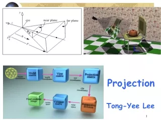
Projection. Overview Orthographic projection Perspective projection OpenGL projection. Turning 3D Objects to 2D Image. In the Viewing lecture last week, we experienced the use of transformations that take objects from World Space to View (Camera) Space

E N D
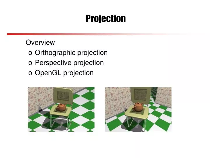
Projection Overview • Orthographic projection • Perspective projection • OpenGL projection
Turning 3D Objects to 2D Image • In the Viewing lecture last week, we experienced the use of transformations that take objects from World Space to View (Camera) Space • We do this by transformations that align the View Coordinate axes with World Coordinate axes • The transformations are represented as matrices • Now we want to transform 3D objects in the View (Camera) Space to 2D Screen Space, in analogous to taking a photo with a camera • We will do this by finding the transformation matrices
Projection • Mapping from 3D to 2D is called projection: • Parallel projection maps objects directly onto the screen without affecting their relative size. Used in architectural and CAD applications where the final image needs to reflect the actual measurements of objects rather than how they might look • Perspective projection gives realistic views, but does not preserve proportions - projections of distant objects are smaller than projections of objects of the same size which are closer to the view plane. This is called foreshortening.
In Orthographic parallel projection, view plane is perpendicular to the direction of projection (think about a torch casting parallel rays on the view place) Oblique parallel projection has view plane at an angle to direction of projection Parallel Projection P1 P1 P2 view plane P2 view plane We shall only consider orthographic projection
Perspective Projection • In a perspective projection, objects are projected onto the view plane along lines which converge at the observer, or Centre of Projection (COP) P1 P1’ COP/ Eye/ Camera P2 P2’ view plane
View Volume (View Frustum) • Realistically, a camera can only take images of objects within a certain distance, and the camera viewing angle is limited • In computer graphics we define a region in the 3D space and call it View Volume or View Frustum, and only objects within this space can be seen on the screen • This means we need to ‘clip’ objects against this View Volume, that is, we need to decide what objects, or which parts of the objects are inside this Volume – there are ‘clipping algorithms’ to do this, which we will look at later in the module
View Volume (View Frustum) • Right now, we want to define this View Volume and see how objects within it can be projected to 2D • Orthographic view volume is a rectangular block defined by near, far, left, right, top and bottom planes • The perspective view volume is pyramid like (with top cut off) defined using field of view or planes(near, far, left, right, top and bottom) • Left, right, top and bottom planes all pass through the center of projection (COP, usually coordinate origin) • Near and far planes are parallel to the image plane - we can move the image plane forward and backward along the z axis and still get the same image, but of different scale
yv Viewing Frustum View Volumes Image Plane Q Eye Position P Q zv xv yv P zv xv Eye Position Image Plane Viewing Frustum Field of view
yv Viewing Frustum How Do We Do Orthographic Projection? Image Plane Q Eye Position P Simple! Looking along z-axis we can see that Q is a 3D point in camera space, P is its 2D projection and xP = xQ, yP = yQ(P and Q have the same x, y) zv xv yV P(xp, yp) xV
Orthographic Projection Matrix • But transformations are usually represented in matrix form, from this, to this xP = xQ yP = yQ zP = d xp yp zp 1 xQ yQ zQ 1 1 0 0 0 0 1 0 0 0 0 d/zQ 0 0 0 0 1 = This matrix can transform 3D points to 2D
Local Coordinate Space World Coordinate Space View Space Canonical View Volume Display Space OpenGL Projection • An OpenGL projection matrix takes points in view space and converts them to points in normalised or canonical space • This happens when GL_PROJECTION is called • The canonical space is a 2x2x2 cube: X=[-1,1], Y=[-1,1], and Z=[-1,1] • This is because only parallel projection is needed in canonical space
OpenGL Orthographic Projection Matrix • When you call GL_PROJECTION and mention ‘orthographic’, OpenGL use a matrix to transform your object to canonical space, e.g.
Perspective Projection • Assuming the origin of view space is at the center of projection (the eye), and the image plane is focal distance d away from the origin • Where does a point in view space end up on the image plane? P(x,y,z) P(xp,yp) y P(x,y,z) -z P(xp,yp) x
Perspective Projection • Looking along X axis, red and green similar triangles give: P(x,y,z) P(xp,yp) y y P(x,y,z) P(xp,yp) -z x o -z d View Plane
OpenGL Perspective Matrix • But OpenGL uses a perspective projection matrix to transform view frustum to canonical (normalised) space, e.g., • Never mind how the matrix is derived!
Objects Are Also Transformed • When transforming view frustums, either parallel or perspective projection, to canonical space, the objects are also transformed, e.g., in perspective projection
Finally... • The last step is to position the picture on the display screen • This is done by a viewport transformation (call glViewport() in OpenGL) where the normalized projection coordinates are transformed to display coordinates • Parameters of glViewport() describe position of screen space within the window and the width and height of the screen, measured in pixels on the screen y screen x
OpenGL Projection • Set matrix mode glMatrixMode(GL_PROJECTION) • Define frustum glOrtho(left, right, bottom, top, near, far) This produces an orthographic matrix for orthographic projection. The current matrix is multiplied by this matrix and the result replaces the current matrix glFrustum(left, right, bottom, top, near, far) This produces a perspective matrix for perspective projection The current matrix is multiplied by this matrix and the result the current matrix gluPerspective(fov, ratio, near, far) does the same • Field of view, fov, or view angle in y direction • Aspect ratio, ratio, should match window aspect ratio • Near and far planes, nearand far glViewport(x, y, width, height) • This transforms objects from camera space to screen space. (x,y) is lower left corner of screen • width and height specify screen dimension