Download

1 / 27
300 likes | 486 Vues
Broadband Cavity Enhanced Absorption Spectroscopy With a Supercontinuum Source. Paul S. Johnston Kevin K. Lehmann Departments of Chemistry & Physics University of Virginia.

E N D
Broadband Cavity Enhanced Absorption Spectroscopy With a Supercontinuum Source Paul S. Johnston Kevin K. Lehmann Departments of Chemistry & Physics University of Virginia
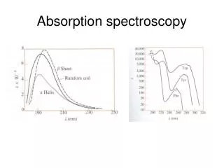
In the past decade, the use of low loss optical cavities have become widely used to achieve high sensitivity absorption spectroscopy. Multiple variants, including Cavity Ring-Down Spectroscopy NICE-OHMS Cavity Enhanced Absorption Spectroscopy Dielectric Super Mirrors ( < 100 ppm reflection loss) have been key to the sensitivity enhancements of these methods.
Limitations of Super Mirrors • High reflectivity bandwidth of dielectric mirrors limited to a few % in wavelength • They are 1-dimensional photonic crystals. • One can extend bandwidth by chirping the coatings of the layers but this increases loss and dramatically reduces damage threshold • High reflectivity (>99.9%) is only available for far less than an octave in the spectrum. • Need to use reflectors that do not depend upon interference.
Brewster Angle Prism Retroreflector Ring-down Resonator Output Input q b q b P- polarization 6 meter radius of curvature G. Engel et al., in Laser Spectroscopy XIV International Conference, Eds. R. Blatt et al. pgs. 314-315 (World Scientific, 1999).
Advantages of Prism Cavity • Wide spectral coverage - Simultaneous detection of multiple species • Compact ring geometry (no optical isolation required) • No dielectric coatings (harsh environments) • Coupling can be optimized for broadband • Analysis: Paul S. Johnston & KKL, Applied Optics 48, 2966-2978 (2009)
What are loses of Prism Cavity? • Deviation from Brewster’s Angle • Surface Scattering at optical surfaces • Need super polishing • Bulk Absorption and Scattering Losses • Rayleigh Scattering Dominates for fused silica prisms • Birefringence which converts P -> S polarization • Strain must be minimized.
Surface Scattering Losses • Surfaces super polished to s = 1 Å rms • Loss for each total internal reflection: • (4 n cos() / 0)2 =0.15 ppm for 0 = 1 mm • Loss for each Brewster Surface: • Total < 2 ppm/prism at 1 mm. • Finite angular spread of beam leads to <0.02 ppm loss
Bulk Loss • For fused silica, scattering loss dominates absorption for l < 1.8 mm. • small residual [OH] absorption near 1.4 mm. • Prisms made of Suprasil 3001 which has [OH] < 1 ppm • Rayleigh scattering loss ~ l0-4 • loss of ~ 1 ppm/cm @ 1 mm. • Intracavity pathlength of 3.8 cm for our prisms (16 mm length on short side)
Source for Broad Bandwidth Coherent Radiation:Supercontinuum Photonic Crystal Fibers • Material: Pure Silica • Core diameter: 4.8 + 0.2 µm • Cladding diameter: 125 + 3 µm • Zero dispersion wavelength: 1040 + 10 nm • Nonlinear Coefficient at 1060 nm: 11 (W·Km)-1 www.crystal-fibre.com
Supercontinuum Generation • Fiber • Length = 12 m • Input • Average power: 1.0 W @ 1064 nm • Rep rate: 29.41 kHz • Pulse energy: 34 mJ • Peak power: 3.4 kW • Output • Average output power: 0.270 W (at input polarizer) • Loss of ~50% power through polarizer
Higher Power Supercontinuum from mode lock Nd:YAG laser • Input: • Spectra Physics Vanguard. • 80 MHz/ 30 psec pulse train • Average power: 9.5 W @ 1064 nm • Peak power: ~10 kW • Supercontinuum Output • Average output power: 3.2 W • With optimized fiber, we expect higher conversion
Paul S. Johnston and KKL, Optics Express, 16, 15013-23 (2008) Broadband system using white lightfrom photonic crystal fiber
Observed Cavity Loss Model:
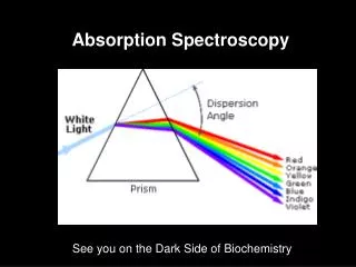
Cavity enhanced spectroscopy Measure time integrated intensity • Advantages • Relatively high sensitivity • Simpler set up • Sensitivity limitations • Residual mode structure • Laser noise Berden, G.; Peeters, R.; Meijer, G. Int. Rev. Phys. Chem.2000, 19, 565.
Allan Variance • Read CCD every 10 sec for ~8 hrs • Successive CCD readings were binned for time intervals of Dt. • Variance calculated for ratio of spectra for each Dt pair. • Minimum noise point: 90 min 650 nm
Current Status • Absorption Sensitivity 5.88x10⁻⁹ cm-1 • Equivalent to 1.6 x 10⁻⁹ cm-1 Hz-1/2 • Shot noise limited • Shot noise limit extends to ~90 min integration. • Resolution ~0.05 cm-1 (2 GHz) • Close to diffraction limit for 25 cm grating used • Bandwidth vs. resolution limited by CCD
Improvements.... • Expand simultaneous spectral coverage • Plan to use FTIR to cover entire spectral range of super continuum. • Considering construction of Echelle Spectrograph which will allow efficient use of most of CCD pixels. • CaF2 prisms should allow extension into the UV, BaF2 prisms into the mid-IR.
I admit it; I’ve got comb envy! • As already discussed by Jun Ye, a vastly higher power can be coupled in with a frequency comb • Hansch’s group has shown how a vernier principle can be used to get single comb resolution with a modest resolution spectrograph • Dispersion limits the spectral width that can be simultaneously coupled into the cavity
Acknowledgments • Dr. Paul Rabinowitz • Tiger Optics research team • University of Virginia, National Science Foundation, and the Petroleum Research Fund.
White light sources http://www.crystal-fibre.com