Download
1 / 42
460 likes | 605 Vues
Clinical Neutron Therapy Center. Donna Kubik Spring, 2005. CNTS. With special thanks to Ruedi Risler and Steve Daley for technical guidance and friendship!. CNTS.

E N D
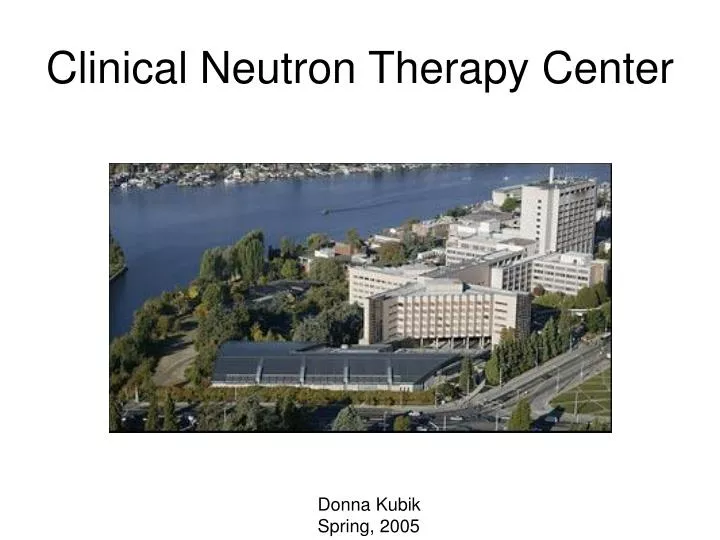
Clinical Neutron Therapy Center Donna Kubik Spring, 2005
CNTS • With special thanks to Ruedi Risler and Steve Daley for technical guidance and friendship!
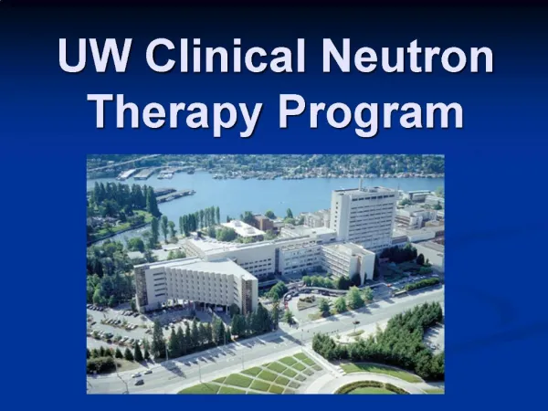
CNTS • The Clinical Neutron Therapy System (CNTS) at the University of Washington is a computer controlled cyclotron and neutron therapy treatment facility • Located in University Hospital on Portage Bay in Seattle, Washington
CNTS • CNTS provides proton beams which are used to produce • fast neutrons for cancer treatments • proton and other charged particle beams for medical radionuclide production • particles for experiments in medical physics and radiobiology
Scanditronix MC50 • The CNTS system uses a Scandtronix MC50 cyclotron • Accelerates protons to 51 MeV • Can also accelerate deuterons, alpha particles (4He++) and 3He++ ions
Scanditronix MC50 • A linear accelerator could be used, but a cyclotron, being a circular machine, is more compact • This is an advantage in a hospital-based facility when space is often restricted
Major components • Magnet • Keeps particles on circular orbit • Focuses beam • RF • Accelerates beam
Major components • Ion source • Produces particles to be accelerated • Extraction system • Guides particles out of the cyclotron • Vacuum system • Cooling system • Diagnostics (beam probe)
Scanditronix MC40 The MC40 is a lower-energy cyclotron; Similar to the MC50 Zoom on next slide
Scanditronix MC40 cyclotron Orange part is magnet yoke Wire at top is ion source Tall square columns are RF cavity tuners Extraction line with quad triplet Green things are vacuum valves
Ion source • Dual ion source • The gas containing the desired ion (hydrogen at CNTS) is admitted into the chimney in the center of the machine • A negative voltage is applied between two cathodes at the top and bottom of the chimney creating an arc • The magnetic field causes the electrons (in the arc) to spiral up and down the chimney
Ion source • The spiraling electrons collide with gas molecules, ionizing them in the process • The positive ions are extracted through a narrow slit in the chimney by the electric field from the dee tip whenever the dee is negative
RF system • In early cyclotrons, there were 2 accelerating electrodes that were formed like the two halves of a closed pillbox cut in half • Because of their shape, they were called dees
RF system • The name has remained even though the shape of the accelerating structures of modern machines look quite different • The MC50 has two wedge-shaped dees with a tip angle of 90 degrees
RF system • The particles are accelerated by the electric field at the edge of the dees • The polarity of the field is alternated such that a particle encounters an accelerating field each time it crosses a dee boundary • Inside the dee (and in the 90 degree system also between the dees) there is a field-free area where the particles just coast.
Harmonic modes • A cyclotron can be operated in several harmonic modes • In the first harmonic mode, the frequency of the acceleration voltage equals the revolution frequency of the particle, in the second harmonic mode, the RF freq is twice the revolution freq, etc
Push-pull mode • At CNTS, the protons are accelerated in the first harmonic mode, so the RF frequency is equal to the revolution frequency • The dees are operated in push-pull mode • This means that at any given moment one dee has the opposite polarity from the other
Cyclotron principle • The RF frequency, w, equals the revolution frequency • Notice that, at non-relativistic velocities, the revolution freq is independent of R
Cyclotron principle • But, to be relativistically correct, the mass should be replaced by • As the particles speed up, the revolution frequency decreases and the particles are no longer in the correct phase relative to the alternating dee voltage
Cyclotron principle • Protons become relativistic at about 30 MeV • At 50 MeV, b=0.30 • So, at CNTS, relativistic effects are important • But with a fixed RF frequency, how can the beam be kept in synch with the alternating RF?
Cyclotron principle • The solution is to increase the magnetic field as a function of radius in order to compensate for the relativistic effect
Magnet • The magnetic field is created by an electromagnet • 90 ton steel yoke • Main coil with current up to 900 A • Average field 1.8 Tesla • 1.4 m diameter pole pieces
Shaping the magnetic field • The necessary increase of field with larger radii is accomplished by • Proper shaping of steel • 10 concentric circular coils in upper and lower pole pieces • The current in each of these 10 pairs can be adjusted individually
AVF • All modern cyclotrons are azimuthally varying field (AVF) machines • The magnetic field is not uniform in all azimuthal directions • The field strength varies as the particle progress along their circular orbits • This results in focusing and defocusing of the accelerating beam (Thomas focusing)
AVF • This azimuthal field shaping is done with steel shims (hills) where the pole gap is reduced and the field strength is increased. • These hills are separated by valleys • The MC50 has 3 spiral shaped hills and three valleys
Harmonic coils • Located in the three valleys are four sets of harmonic coils • Harmonic coils A-C are used to correct particle paths to help keep the particles centered in the machine
Harmonic coils • Harmonic could D (and circular coil 9) are used to excite coherent radial oscillations of the beam just inside the extraction radius
Extraction • This resonance increases the spacing between successive turns. • A narrow copper septum separates the particles in the last full orbit from the particles being guided out of the machine. • The beam is guided out of the machine by an electric field between the deflector and (grounded) septum and some magnets internal to the machine • It is possible to achieve extraction efficiencies of 60-85%
Extraction • The mean extraction radius of the MC50 is 58.2 cm • This radius, together with the RF frequency, determines the energy of the beam
Energy calculation for cyclotron • The final energy of the particles is determined by • Velocity, v • RF frequency, f • Extraction radius, R • With g and the rest mass, Eo, the kinetic energy, T, of the particle can be calculated
Energy calculation for cyclotron • For a 50 MeV beam, the RF freq. is 25.9 MHz, peak dee voltage of 40kV • This means the particle make about 440 turns during acceleration • The RF freq is well known, but the extraction radius is not as well known
Beamlines To patients Isotope production
Be target • The protons hit the Be target • The charged fragments (which contain protons from the Be nucleus) have a short range and are stopped in the target assembly • The neutrons are very penetrating and leave the target
Dosimetry system • A dosimetry system is downstream of the target • It is comprised of a transmission ion chamber which measures the intensity of the beam • The ion chamber is connected to an electrometer system which integrates the signal
Dosimetry system • The dosimetry system is calibrated and is used to determine the dose delivered to the tumor and surrounding tissue • For safety reasons, the dosimeter system is split into two completely independent systems with dual chambers, power supplies, electrometers and means to terminate treatments
Multileaf collimator • The neutrons are then collimated and used for the irradiation of cancerous tissue
Protons vs. neutrons • Protons deposit a larger fraction of their energy in a localized spot (Bragg peak), hence are more suited for cancers near sensitive structures as the optic nerve, spinal cord, etc • However, slow-growing tumors spend a relatively short time in the dividing phase of the cell cycle, when they are most sensitive to ionizing radiation (as that of protons and photons) Bragg peak
Protons vs. neutrons • These tumors are more-effectively treated with neutrons. • Neutrons interact with the atoms in a tumor cell via nuclear interactions. • Neutrons don’t just ionize atoms in the tumor cells, but the interactions result in breaking apart the atoms, forming new, or different, atoms
Protons vs. neutrons • But neutrons loose energy more gradually as they pass through tissue (no Bragg peak) • For neutron therapy, it is especially important to minimize the exposure to healthy tissue • Note that, while neutrons (as well as photons) have no Bragg peak, neutrons and photons DO have skin sparing, while protons do not. Neutrons lose energy more-gradually
Isocentric beam delivery • An isocentric beam delivery system is essential so that the patient can be irradiated from several different angles • This concentrates the dose at the tumor and limits the dose to normal tissue • CNTS employs an isocentric gantry system as shown on the right
Isocentric beam delivery • Isocentric treatment can also be accomplished by rotating the patient or rotating the beam. • From a relativistic point of view, it does not matter whether you rotate the beam or the patient. The result is the same.
Isocentric beam delivery • Fermilab’s Neutron Therapy Facility has been doing isocentric treatment with a rotating patient immobilization platform since 1976. • Neutron therapy has been very successful in treatment of many types of cancer