Download
1 / 27
280 likes | 529 Vues
Coating of the CERN SPS main dipoles vacuum chambers: alternative scenarios, logistics. J. Bauche – CERN magnet group. Coating of the CERN SPS main dipoles vacuum chambers: alternative scenarios, logistics. Introduction SPS machine and magnet system overview Goal and restrictive parameters

E N D
Coating of the CERN SPS main dipoles vacuum chambers: alternative scenarios, logistics • J. Bauche – CERN magnet group
Coating of the CERN SPS main dipoles vacuum chambers: alternative scenarios, logistics • Introduction • SPS machine and magnet system overview • Goal and restrictive parameters • Strategy 1: coating in the tunnel • Previous experience • Implementation of the method in the coating project • Rythm, bottlenecks • Pros & cons • Strategy 2: coating in an underground workshop • Previous experience • Workshop • Transport • Rythm, bottlenecks • Pros & cons • Strategy 3: coating in a surface workshop • Previous experience • Transport • Rythm, bottlenecks • Pros & cons • Conclusions and prospects
Introduction • SPS complex: • 14 km of beam lines including the 7 km long synchrotron ring • About 3100 magnets for the whole complex • About 1400 magnets in the ring including 744 main dipoles and 216 main quadrupoles • The main dipoles represent more than 70% of the length of the synchrotron vacuum system, the quadrupoles about 10%
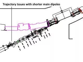
Introduction SPS typical FODO half-cell
Introduction General Overview of the SPS main Dipoles MBA and MBB dipole magnets have similar outside dimensions, but different apertures. Each dipole is a H-type magnet about 6 meter long, 18 tons and consists of two identical laminated half-cores, a coil assembly and a captive stainless steel vacuum chamber. The assembly is welded into a rigid self-supporting unit.
Introduction SPS Bus-Bar System: Powering and Cooling Principles • Main dipole and quadrupole magnets powered and water-cooled through hollow copper bus-bars Powering Principle • The cooling system is equipped with valves for each half-sextant Cooling Principle Diagrams: courtesy of D. Smekens
Introduction Handling and transport of SPS main magnets done with machines so called the ‘Dumont’s’: - Trailers designed for the SPS tunnels, equipped with 2 handling manipulators, - Hydraulic system, not automated - For long distances, we transfer the magnets on standard trailers in the access galleries to win time - 2 of these machines are currently available Installation of main dipole in the SPS Transport of dipole
Introduction Goal and restrictive technical Parameters • Goal • Complete coating of the 744 SPS main dipoles AFAPA and ACARA optimize logistics • Restrictive parameters to total duration of project • Cadency of treatment • If implemented during shutdown periods, duration: standard period is 14 weeks of access in the machine, i.e.10 weeks of effective work (4 weeks are necessary for start-up and end phases of the project) • Availability of the machine w.r.t. other activities (interferences): TBD by priority of this project • Restrictive parameters to cadency of treatment • Time of coating process: 4 days, including cleaning (1 day), installation of equipment - vacuum pumping (1/2 day), coating (2 days) and dismantling of equipment (1/2 day) • Number of equipments available for coating, transport, ancillary: no purchase of additional transport machines • Space available (number of units being treated in parallel) • Manpower (number of teams available for work in parallel (and / or shifts ?) • Working time: 8 hours / day, 5 days / week • Equipment technical limits (e.g. overheating of PU of transport equipment wheels)
Strategy 1: coating in the tunnel • Previous experience • Installation of RF shieldings in the pumping port cavities of the magnet vacuum chambers to reduce the machine impedance between 1999 and 2001 → Method used: 1 over 2 dipoles removed from its position and put in the passageway on the Dumont handling machines to allow accessing interconnections on all the magnets → Figures: • 1200 interconnections equipped during 2 long shutdowns • 370 main dipoles and a hundred of auxiliary magnets removed from their position • Rate of treatment: 3 dipoles / day removed and reinstalled to their position • Time of process / magnet: a few hours, including handlings RF shielding model
Strategy 1: coating in the tunnel • Implementation of the method to the coating project • Idea to take out of its position 1 over 2 magnets to allow access to all vacuum chambers OK • BUT with a coating process time ≈ 4 days, doing it in the same way means to let 370 magnets, 4 days each one, on the Dumont in the passageway. This would destroy the polyurethane wheels of the Dumont’s. Also, since only 2 Dumont are available project would be realized in about 750 days… not realistic! • Alternative: lifting the magnets about 500 mm above their position instead of bringing them in the passageway + stabilizing them with supports in order to free the Dumont + removal of SSS girders Access for coating equipment Insertion SPS typical half-cell
Strategy 1: coating in the tunnel • BUT space available above the magnet is too small to realize that with the Dumont machines • need to purchase or manufacture a lifting device that ‘pushes’ instead of ‘pulling’ (like a lifting table) SPS tunnel cross-sections @ dipole position
Strategy 1: coating in the tunnel • Sequence of the operations Day 1 Day 2 Day 3 Day 4 Installation & puming Cleaning Coating Dismantling Main quadrupole Main dipole Schematic of the work site in 6 half-cells
Strategy 1: coating in the tunnel • Bottlenecks • Required number of pumping /coating equipments • Space available for work and for rotation of the equipment • Rhythm • Assuming realistic cadencies, i.e. in 4 days: • 1 team disconnects-reconnecst12 dipoles from the busbars; • 1 team lifts and puts back in place 12 dipoles ; • 1 team removes-reinstalls 6 SSS girders with auxiliary magnets; • 1 team cleans 24 dipole vacuum chambers; • 1 team aligns 6 half-cells • Assuming also: • 15 supporting units are necessary (3 for rotation) • 21 pumping / coating equipments are necessary (realistic ?) • Rhythm = 6 magnets / day • Project completed in 120 working days
Strategy 1: coating in the tunnel • Pros • Minimize handling of magnets to the very minimum (lift and put down) • No transport • Reasonable interference with other activities (stays localized in a sector) • The method gives access to both sides of each quadrupole that could so be treated too (≈10% of SPS ring vacuum length) • Quadrupoles stay in place survey reference kept, time won for alignment • Cons • Radioactive environment, important exposure of the workers • Space available is small risks increased + equipment has to be adapted (is it possible ?). Rotation of the equipment would be difficult • Requires a lot of pumping /coating equipments in parallel • Access to vacuum chambers not so easy • Requires numerous specific supporting structures
Strategy 2: coating in an underground workshop • Previous (and current) experience • MBB manifold consolidation program 2006 - 2008: complete refurbishment of all the manifolds on the MBB magnets equipped with Lintott coils in operation in the SPS → Method used: magnets removed from their positions and transported with the Dumonts and trailers to ECX5 cavern converted in radioactive workshop → Figures: • 255 magnets treated over 3 shutdowns (about 70 days of work in the workshop) • Refurbishment rate: 4 magnets / day • Time of process / magnet (machining, welding, assembly and tests): ≈ 3 hours Before After
Strategy 2: coating in an underground workshop • Workshop → Radioactive workshop in ECX5 cavern - Underground instead of surface: to limit the risks of transport and handlings and to win time - In the ECX5 cavern (ex-UA1 experiment): → polar 40 tons crane available (refurbished in 2007) → enough space to refurbish 4 magnets / day → very low radiation level ECX5 worshop for MBB manifold consolidation (top view) ECX5, workshop side ECX5, storage side
Layouts of Underground Worshop Underground Workshop ECX5 + 300 m2 concrete screed ECA5 460 m2 Capacity of workshop: 24 magnets
Strategy 2: coating in an underground workshop Transfer Dumonts ↔ trailers - Possible in all access points - Ttransfer ≈ 20 min • Transport Journey with Dumont machines - Average speed ≈ 2 km/h - T1 sextant = 36 min Sector type 3 Sector type 4 Journey with trailers - Average speed ≈ 5 km/h - T1 sextant = 14 min Sector type 6 Sectors type 2 Sectors type 1 Sector type 5 ‘Equi-time’ positions between 2 sextants : positions from which transferingDumonts ↔ trailers in the previous or in the next point results in the same total time of transport
Strategy 2: coating in an underground workshop • Bottlenecks • Number of Dumont vehicles available (2) • Required number of coating equipments • Thespace available in ECX5 - ECA5 • Rhythm • Assuming same rhythm for connection to busbars, alignment and vacuum connections than strategy 1 • Assuming 18 equipments of coating are necessary • Assuming 1 pumping unit could pump 6 magnets in parallel only 3 pumping unitswould be necessary • Assuming 2 transport teams work in parallel with 2 Dumont + trailers (3 magnets / day removed – reinstalled per team realistic following last consolidation experience) • Rhythm = 6 magnets / day • Project completed in 120 working days
Strategy 2: coating in an underground workshop • Pros • Workshop environment with much lower radiation level than in the tunnel • Much space available, possibility to pile up magnets • Equipment regrouped in a dedicated workshop, improved safety and ergonomics • Possibility to pump more magnets in parallel with less pumping units than in strategy 1 • Same with cleaning units • No special supporting structure required • Cons • Interference between transport and other activities in the tunnel • Risks inherent to crane handling and transport • Need for transport teams in addition to coating teams increase costs • No crane available between ECA5 and ECX5 we would need for a portico crane or for air cushion motioned supporting structures
Strategy 3: coating in a surface workshop • Previous experiences • None in big projects, only preventive and corrective annual magnet exchanges (5 to 10 / year) • → Method used: magnet removed from its positions and transported with the Dumont to BA3 equipment lift and pulled by electro tractor to magnet workshop in bdg. 867, replaced by a spare • Transport BAs equipped with equipement lifts: BA2, BA3 & BA6 - Tlift ≈ 30 min Transfer ECX5 to ECA5 and lifting to surface with ECA5 crane - Tlift ≈ 10 min • Workshop in BHA5 if we open the concrete block wall between ECA5 and ECX5, we can lift the magnets with the BHA5 crane (no more need for lifts)
Strategy 3: coating in a surface workshop • Bottlenecks • Number of Dumont vehicles available (2) • Required number of coating equipments • Required number of lorries and transport teams in addition to the logistic in the tunnel in case we would choose BA2 or BA6 equipment lift • Rhythm • Assuming same rhythm for connection to busbars, alignment and vacuum connections than strategy 1 and 2 • Assuming same cadencies of transport in the tunnel than strategy 2 • Assuming additional teams and lorries are available in case we would choose to pass by the road (not necessary if we transit by ECA5 to surface) • Rhythm= 6 magnets / day • Project completed in 120 working days
Strategy 3: coating in a surface workshop • Pros • Work in a non radioactive environment (but not so different than in ECX5), and not underground access more easy to workshop • We could find a bigger workshop in surface if necessary (e.g. BHA5) • Cons • Need to implement an important logistic in surface in addition to the one underground more difficult to manage, time consuming and costly • Increase of risks inherent to handlings and transport compared to strategy 1 and 2 + transport of radioactive material on the road not recommended • If we would use the lifts, they could need to be refurbished • If we would pass by the ECX5 - ECA5 and use the BHA5 as a workshop, we would have to stock the 30 blocs of 72 ton of the wall that separates ECX5 and ECA5 outside the building need for a mobile crane (1 week of work for dismounting)
Conclusion • Summary • If we would run the project during shutdown periods, 3 shutdowns would be necessary for any strategy. But since in big projects like this, things are never straight forward, we have to consider 25 % of safety margin 4 shutdowns would be realistic, moreover for strategies 2 and 3 that interfere with other activities
Conclusion • So, which strategy? • This is a first draft ! We first need to fix the following parameters: • Operating mode, process duration and conditions needed for each operation • Deadline for the project to be completed • Resources allocated to the project (budgets, manpower) • Will this project be implemented during shutdowns ? If yes, what will be the durations of the shutdown periods and the priority of this project w.r.t. other activities ?
Conclusion • Thank you for your attention !
References • Reducing the sps machine impedance, P. Collier, M. Ainoux, R. Guinand, J-M Jimenez, A. Rizzo, A. Spinks, K. Weiss • New Strategy for the Repair of SPS Dipole Water Manifolds, J. Bauche, W. Kalbreier, D. Smekens(EDMS Doc. No.: 783313) • Projet de Consolidation des Dipôles Principaux du SPS. Remplacements des manifolds de refroidissement des bobines dipôles, D. Smekens (EDMS Doc. No.: 782003)