Download
1 / 34
340 likes | 550 Vues
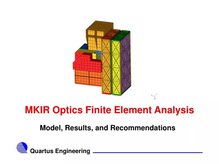
MKIR Optics Finite Element Analysis. Model, Results, and Recommendations. Overall FEM Summary. Comprehensive finite element model (FEM) generated for entire experiment 133,600 nodes 65,700 elements (parabolic formulation) All critical components explicitly modeled where possible

E N D
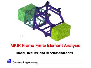
MKIR Optics Finite Element Analysis Model, Results, and Recommendations
Overall FEM Summary • Comprehensive finite element model (FEM) generated for entire experiment • 133,600 nodes • 65,700 elements (parabolic formulation) • All critical components explicitly modeled where possible • Some components represented using lumped masses and rigid elements
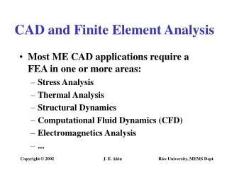
Boundary Conditions • Model is grounded at top of ISS/VJ Interface • One G gravity load applied in three directions • Vertical (+Z direction) • 70 degrees towards +X axis • 70 degrees towards +Y axis • All components attached directly where appropriate
AO Bench Optics • Not explicitly modeled • Used lumped mass and rigid elements • Newport bench modeled explicitly with orthotropic core
Detailed FEMs of Components • Most major components are explicitly modeled • Some simplifications made • Holes in wheels neglected; density adjusted • Some bearings modeled as equivalent material • Some bearings modeled with springs • Bolted interfaces not explicitly modeled • Assumed that bolt margins are sufficient • Assume proper bolted design yields ‘continuous’ interface
Cameras Modeled With Detail • Mounts are explicitly modeled
Camera FEM Detail • Flexures modeled explicitly • Key component
Generated Data • Translations and rotations recovered at critical locations • All components in AO Bench • Focal plane mask • Spider wheel • Pupil wheel • Diachroic • Red and Blue wheels, fold mirrors, OAP mirrors and detectors
Displacements Generated • Typical displacement data • 70 degree X case
Stresses Recovered in Model • Stress in all components recovered • Margin against gravity load show no problems • MoS > 10 for stress • Problem is stiffness driven • Examination of vacuum jacket under pressure not conducted • Design sizing presumed sufficient
Y Direction Loading Stress in Blue Camera • Flexures show highest stress
X Direction Loading Stress in Blue Camera Camera mount show highest stress
Modal Frequencies Calculated • Modes calculated for entire structure to 100 Hz • First mode at 23.8 Hz for focal plane mask (torsion) • May be low due to some modeling assumptions • May warrant further examination • Second and third modes at 43.1 and 43.5 Hz FPM bending modes
Conclusions • FEM of total model indicates structure is stiffness driven • Stresses all low • High Margins • First mode is in focal plane mask • No one component responsible for majority of displacements