Download
1 / 17
170 likes | 440 Vues
MICE Target Status . P J Smith CM 25 Wed 4 th November 2009. Overview. Several New Targets have been built and tested. T1, T2 and T2 Mk II. Target T1 is now installed on ISIS and has been instrumental (along with all the other hardware!) in commissioning the MICE beam line.

E N D
MICE Target Status P J Smith CM 25 Wed 4th November 2009
Overview • Several New Targets have been built and tested. T1, T2 and T2 Mk II. • Target T1 is now installed on ISIS and has been instrumental (along with all the other hardware!) in commissioning the MICE beam line. • Wear problems with the bearings on T2 and T2 mkII have demonstrated that there may be some subtle issues to be addressed with the reproducibility of the manufacturing process and that some development work still needs to be done to both understand and mitigate this problem. • Further development work with alternative bearing materials is underway. • Work Continues in developing a new control system for the target mechanism. • Plots Produced by P.Hodgson – He deserves the credit for this! P. J. Smith - University of Sheffield
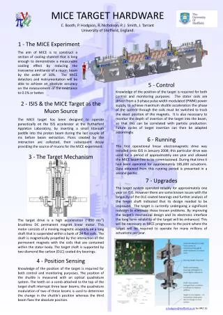
Target Redesign • Over the preceding months much effort has been put in by J. Tarrant at RAL in a redesign of the target’s mechanical components. Design components that could be reproducibly made to exacting standards. The Key changes implemented were: The titanium Shaft is nowconstructed from 2 pieces. The previous cruciform cross-section section was lost and replaced with a tubular section. This meant that the target shaft can now be manufactured to a much tighter tolerance to ensure that it runs straight and true. • The bearings were redesigned to accommodate the changes to the shaft and an anti-rotation device was built into the top bearing (this mated with a flat surface on the upper section of the shaft. • The target housing was redesigned so that the shaft could be aligned to the centre of the stator with a high degree of accuracy. P. J. Smith - University of Sheffield
Target Build 2 Identical stators were built at Sheffield. – Coil Stack, Heat sink shims and cooling jacket 2 shafts, 2 sets of bearings and 2 stator housings were produced at RAL. The shaft and bearings were put through the DLC treatment process at the same time. TecVacconfirmed that we had a 4 µm DLC coating on the treated pieces. Metrology indicated that one shaft was slightly misaligned 200 µm out of true along its length. (The 200 µm measured from ends so real effect is less that half this.) Decision was made to use the straighter shaft in T1 and to straighten the second shaft for use on T2 in R78. P. J. Smith - University of Sheffield
T1 Commissioning In August 2009 Target 1 was installed in R78 and a commissioning run of 50K pulses was completed (22/08/09) running at 1~Hz. Strike Distance ~44 mm. Beam Centre Distance 20 mm. ∆ ~ 0.6mm Diagrams Taken From MICE Note 270. T1 performed well during commissioning and was subsequently installed on ISIS. I shall say more about T1 later. P. J. Smith - University of Sheffield
T2 Commissioning T2 was installed in R78 and operated where it was immediately obvious that it was not functioning correctly. T2 was run for a total of only ~1000 actuations before it was dismantled. The Finger-like projections on RH plot are due to a difference in the way that the minimum depth has been extracted from the DAQ in this plot. It is the baseline width of the plot that indicates that there is a problem. P. J. Smith - University of Sheffield
T2 Commissioning T2 was subsequently dismantled and the following was found: • A very small amount of particulate debris • Shaft felt ‘sticky’ through its travel • Significant wear on bearing surfaces relative tothe small number of actuations Significant Effort was put into analysing the fine details of the bearing failure and a 33 page report describing this analysis is available in the form of MICE Note 269. - J. Tarrant. The conclusion from the analysis was that the DLC coating had failed to adhere to the bearing surfaces. It was also considered possible at the time that the wear rate could have been exacerbated by the slight bend in the shaft of T2. A third shaft and set of bearings were manufactured. Ensured that the shaft straightness was better than T1 & polished out all grinding features (optical microscopy inspection). The same stator body was used, (hence T2 mark 2) and was operated in the middle of October. P. J. Smith - University of Sheffield
T2 Mark II Commissioning T2 mark II was installed in R78 on the 14th October. It was immediately clear that this target was showing the same unusual behaviour seen by T2. However the decision was made to continue running the target to ascertain whether : the target would ‘bed’ in. b) to see if anything new could be learnt in the data stream.... The target was run for 80K pulses before being stopped. A missed pulse is a missed trigger because the target controller is busy performing a positional correction. It does not mean that the target was dropped! Anything below a background of five is not plotted P. J. Smith - University of Sheffield
T2 Mk II Analysis After 80K pulses the target was dismantled and inspected. - Like T2 the shaft felt ‘sticky’ through its travel. - Clear evidence of DLC wear as black residue could be wiped off of the contact surfaces. - Manual inspection showed significant wear on the bearing surfaces, however the shaft looked in good condition. (Bear-in(g)! mind - Bearings see 8x as much wear) Subsequent microscopy examination has revealed that the DLC coating had failed on the bearing surface. Question. Why is T1 working so well, whilst T2 and T2 mark II failed so quickly? P. J. Smith - University of Sheffield
Development Plan There is NO smoking Gun; a lot of care was taken in ensuring that the stators were built identically. Two fold approach to pursue: First Approach To look at the stator coil stack construction and to do a more detailed analysis of the magnetic field structure within the stator. How sensitive are the non axial forces wrt differences between coils and relative coil positioning (we already know that the coils are well aligned – so we are looking at subtle issues?) Evidence? - T1 runs a lot more quietly that T2. Why is this? - Bearing Wear is not uniform around the circumference of the bearing but shows evidence of being ‘pulled’ to one side. - Permanent Magnets have been field mapped and look ok to within resolution obtained but this doesn’t rule out deviations. -The coils are not ‘perfectly’ manufactured. We may be able to produce better coils, but will this will make any significant difference? It isn’t possible to produce a ‘perfect’ stator but what arethe minimum tolerances that can be reasonably obtained? P. J. Smith - University of Sheffield
Development Plan Evidence also suggests that whilst DLC on DLC has shown some success, this success is not reproducible. Are we running at the limit of what DLC on DLC can deal with where small differences between builds are having a significant effect on stator lifetime? Concerns about problems with plasma deposition of DLC inside concave surfaces? Second Approach: To test new bearing materials in an attempt to find a material that demonstrates improved longevity, performance and that is less sensitive to subtle variations between stator builds. (Accepting that it is impossible to build two exactly identical stators and that they can only be built to within tolerances.) New Bearings will be made from Vespel and Torlon. (Rad Hard Plastics) Vespelhas been used successfully with non-lubricated mechanisms in the space science division. These bearings will be tested in R78 in Feb 2010. P. J. Smith - University of Sheffield
T1 Diagnostics As the behaviour of T2 and T2 mk II was indicative that the target bearings were failing, this can now be used as a diagnostic on T1 on ISIS. If the same symptoms are observed on T1 then this will indicate that the time has come to stop using it. T1 Stator ∆ ~0.4 mm A few hundred calibration pulses at a fixed dip depth can be used to characterise the behaviour of the target. T2 Stator P. J. Smith - University of Sheffield
T1 Success! Despite the problems with T2, permission was given to operate T1 within ISIS for an initial 50,000 pulses with further pulses being granted based upon T1 performance. Target Studies. New record for deliberate sustained beam-loss production! MICE BEAMLINE BEING COMMISSIONED! P. J. Smith - University of Sheffield
T1 Success! The new split bank PSU has worked well and combined with the redesigned shaft this has enabled the target to achieve a much higher insertion acceleration. In principle this will allow the target to take more beam-loss when ISIS is operating at 50 Hz. Acceleration Data From T1 This data compares favourably to the 916ms-2 for the previous target installed on ISIS. P. J. Smith - University of Sheffield
T1 Success! 300 Mev/c – to – beam 330 MeV/c – to –beam - decay solenoid on. We have now been given permission to run the target for an unspecified number of pulses conditional on calibration plots being produced and a visual inspection of the target port every 50,000 actuations. Calibration Plots are produced every shift. (Similar to those shown earlier) P. J. Smith - University of Sheffield
Control Upgrade • The target electronics is currently undergoing a radical redesign so that it can be integrated into the MICE control system/DAQ. • The first phase of this redesign involved migrating the current controller over from a microprocessor system to an FPGA. • The FPGA board being used has an integrated USB controller. The USB functionality will allow the target controller to be operated from a GUI in the MLCR. • Afterwards the USB functionality will be ‘connected’ to the control firmware in the FPGA and the GUI interface can then be used to operate the target. Both the USB code and the GUI has been already been coded at Imperial with James Leaver being responsible for the latter. We are optimistic that the first stage of the upgrade will be completed and installed at ISIS in the first quarter of next year. P. J. Smith - University of Sheffield
Conclusions T1 is a success and has been used in the recent MICE beam-line commissioning. T2 and T2 Mark II have failed but the mode of failure is clearly subtle: Further investigations into the magnetic uniformity of the stators are being initiated in parallel with the trialling of alternative bearing materials. New radiation hard plastic bearings will be trialled in R78 in ~Feb 2010. The Failure of T2 has enabled a ‘fingerprint’ of this particular failure mode to be established. This fingerprint has enabled us to continue to run T1 as we now have a mechanism to monitor T1 for this particular failure mode. P. J. Smith - University of Sheffield