Download
1 / 21
210 likes | 486 Vues
Lorentz & Windmill Revisited. SVD Meeting. WRONG. Ramo‘s Theorem. Discussion in January 2010. Citation of page 3:. Electrons are all collected by same n-side electrode Tilt should focus holes to obtain narrow p-side clusters. Simon Ramo (1939): i = q v / d (d…sensor thickness)

E N D
Lorentz & WindmillRevisited Markus Friedl (HEPHY Vienna) SVD Meeting
WRONG Ramo‘s Theorem Discussion in January 2010 • Citation of page 3: • Electrons are all collected by same n-side electrode • Tilt should focus holes to obtain narrow p-side clusters • Simon Ramo (1939): i = q v / d (d…sensor thickness) • Current is induced by the motion of carriers, not their collection at electrodes • Thus we always have to consider both electrons and holes regardless of p- or n-side readout • Additional information e.g. by H. Spieler:http://www-physics.lbl.gov/~spieler/physics_198_notes_1999/PDF/IX-1-Signal.pdf Markus Friedl (HEPHY Vienna)
New Consideration Discussion in January 2010 Huge electron spread No hole spread Little electron spread Moderate hole spread Markus Friedl (HEPHY Vienna)
New Origami and Windmill Orientation Origami+Windmill Layer 6 Origami Orientation Discussion in January 2010 Markus Friedl (HEPHY Vienna)
Situation after January 2010 • Results were frozen and written in the TDR • Immanuel made mechanics drawings based on that scheme • Longest Origami was designed accordingly • During Nagoya B2GM, Samo Korpar said he doubts correctness of results written in TDR • Topic was also picked up to Ushiroda-san • Recently, Tsuboyama-san surveyed papers on the topic Markus Friedl (HEPHY Vienna)
Tsuboyama-san‘s Paper Survey • If the theory in Belle2 TDR is correct, it means that CMS and ATLAS chose wrong direction. • Should we change the direction? • YES: We gain in layer 3 and in PXD. • Better resolution in L3. • Larger cluster size in PXD. • Keeping the present geometry, we should prove using simulation with correct treatment of Lorentz angle and compare two cases. • For this study, we do not have to change geometry. Just flip magnetic field in the MC. • Cost of flipping • Design of SVD by immanuel • Prototypes of ORIGAMI PCB. Are they really wrong? Markus Friedl (HEPHY Vienna)
ATLAS and CMS • Both ATLAS and CMS trackers use n-bulk Silicon with p-strips (same as the Belle II SVD) • CMS Note 2008/006 says: “For the CMS microstrip silicon tracker only the drift of the holes is important, since they are the charge carriers collected on the sensor strips [2].” • No further information given • Ref [2] is the purely mathematical Kotov paper with no practical information given • Very similar statement without further information in ATLAS paper NIM A 538 (2005) 384–407 Markus Friedl (HEPHY Vienna)
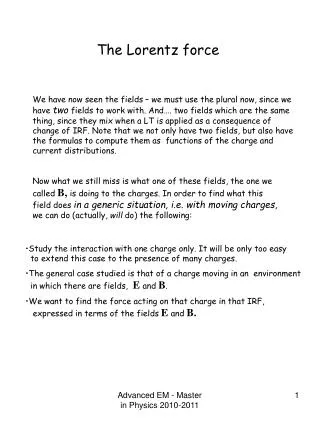
Here is the Answer • I cited this paper already in January 2010:http://www-physics.lbl.gov/~spieler/physics_198_notes_1999/PDF/IX-1-Signal.pdf • If I had read it more carefully (and until the end) then, things may have evolved differently… • Let me try to summarize what I understood Markus Friedl (HEPHY Vienna)
Case 1: Parallel Plate Detector • In this (simple) case, Ramo‘s theory is easy to apply • Both the motion of charges and the induced currents are determined by the electric field • Electrons and holes induce exactly the same integral currents (=charge) on both electrodes (drift times can differ depending on the tilt of the electric field) Markus Friedl (HEPHY Vienna)
Case 2: Strip Detector • Looks similar in the first place, but there is an essential difference: • The motion of charges is still determined by the overall electric field which is similar to the parallel plate case • However, induced currents (and thus charges) are now determined by the weighting field of each strip Markus Friedl (HEPHY Vienna)
What is the Weighting Field? • Fictional field to determine the impact of a moving charge on an individual strip • In order to calculate for a particular strip, set its potential to 1 and all other electrodes to 0 • In case of a practical strip detector (pitch << thickness), the result is strongly nonlinear – key point for charge collection • Why nonlinear? When a charge is far away from the strips, it sees many strips in similar distance, so it must also have similar induction to several strips, which means weak to any individual one Markus Friedl (HEPHY Vienna)
Weighting Potential Example • 300µm thickness, 50µm pitch H. Spieler, see p.8 for URL 50µm strips Detector depth 0µm (junction) readout strip Markus Friedl (HEPHY Vienna)
Application of Weighting Potential readout strip V. Radeka: Low noise techniques in detectors, Ann. Rev. Nucl. Part. Sci., 38:217–277, 1988 Induced current determined by nonlinear weighting field Integral current = 0 Markus Friedl (HEPHY Vienna)
Consequence of Nonlinear Weighting Field • Signal is mostly induced in the vincinity of the electrode • In our case (p-strip, n-bulk), it means holes are dominant • 300µm thickness, 50µm pitch H. Spieler Markus Friedl (HEPHY Vienna)
Summary of Charge Collection • Strip detector case is different from parallel plate case • Weighting field is strongly peaked near signal electrode • Thus most of the charge is induced when the moving charge is near the signal electrode • As a result, most of the signal charge is due to the charge terminating on the signal electrode • For p-strips on n-bulk, holes are dominant • ATLAS and CMS are correct • Belle II TDR is wrong we have to flip the windmill Markus Friedl (HEPHY Vienna)
Lorentz Force on Holes and Tilt • Belle-II SVD configuration is shown • Electrons are not relevant • Tilt should focus holes to obtain narrow p-side clusters Markus Friedl (HEPHY Vienna)
New Consideration Huge electron spread No hole spread Little electron spread Moderate hole spread Markus Friedl (HEPHY Vienna)
Previous Origami and Windmill Orientation Origami+Windmill Layer 6 Origami Orientation WRONG Markus Friedl (HEPHY Vienna)
New Origami and Windmill Orientation New Layer 6 Origami Orientation Origami+Windmill • Implications: • Need to rotate sensors and Origami (APV25-defined numbering mostly opposite global scheme) • New mechanics (support, end rings) • New (mirrored) flex circuit for 6_ce(but anyway need both readout directions) Markus Friedl (HEPHY Vienna)
Origami Configuration • This is still correct (immune to windmill flip), but the APV25 chips now sit on the opposite side of each Origami Markus Friedl (HEPHY Vienna)
Final Remarks • The good thing is that Lorentz angle for holes is just 1/3 that of electrons: H,e=11.5° and H,h=4.1° (calculated) • However: Windmill angle is rather defined by mechanical boundaries than Lorentz angle • I‘d love to do a 2D simulation of charge collection in a strip detector (with weighting field and Lorentz forces), but it needs time and I have to learn how to calculate the field configuration first… • Thanks to Samo for questioning the TDR assumptions. Markus Friedl (HEPHY Vienna)