Download
1 / 100
1.01k likes | 1.2k Vues
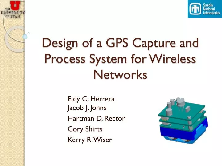
Design of a GPS Capture and Process System for Wireless Networks. Eidy C. Herrera Jacob J. Johns Hartman D. Rector Cory Shirts Kerry R. Wiser. Outline. “Introduction to GPS Tracking System” Cory Shirts “Prototype Design and Construction” Kerry R. Wiser “Embedded Programming”

E N D
Design of a GPS Capture and Process System for Wireless Networks Eidy C. HerreraJacob J. Johns Hartman D. Rector Cory Shirts Kerry R. Wiser
Outline • “Introduction to GPS Tracking System” • Cory Shirts • “Prototype Design and Construction” • Kerry R. Wiser • “Embedded Programming” • Hartman D. Rector • “Transferring GPS Data to a PC” • Jacob J. Johns • “Processing GPS Data” • Eidy C. Herrera
Cory Shirts Introduction to GPS Tracking System
Introduction • GPS tracking system • Design requirements • Design modifications • Component overview
GPS Tracking System • GPS (Global Positioning System) • Consists of constellation of satellites orbiting the earth • Signals from 4 satellites required to determine position
GPS Tracking System • Typical GPS solution • Cold start (no data) needs about 40 s of data • Applications for location tracking in real time • Internal processing
GPS Tracking System • Drawbacks of typical solution • Power consumption • Data storage • Not for portable devices
Portable GPS Tracking • Samples • Taken periodically • Taken when needed (detected motion) • Contain only essential data • Data transferred to PC • Post-processing, web service do the rest
Design Requirements • Low power consumption • Run off 2 CR2 batteries (3.3 Volts) • Last for two weeks • Compatibility with Sandia Stack • Size constraints • Interoperability with other devices in the stack Sandia Stack 0.3” 0.6” 1.25” 1.5”
Previous Design • Design from previous team • Processor with Low Power Modes (LPM) • Accelerometer to trigger wakeup • Small flash chip to store small samples • SiGE GPS receiver
Previous Design Top Side Bottom Side
Design Requirements • Changes needed • Broken Components • Difficult to test • Processor was slow • Flash memory was small From 08-09 Team Sandia Stack
Design Modifications • Our approach • New, faster low power processor • Bigger flash chips • Newer accelerometer model • Use testable prototypes for development Sandia Stack
Prototype Design (Kerry) • Eagle CAD for maintaining schematics and manufacturing parts • Some parts were bought • Assembled some, had some made • List of Prototypes • Accelerometer • Flash memory • SiGE GNSS antenna • Multiplexers
Programming Overview Setup Get info on bad flash blocks if we don’t already have it Setup ADC for Accelerometer Setup external wake-up pin Main Loop Enable wake-up pin Go into LPM3 mode to save power Interrupt once per second to check for movement Disable SiGE Turn off ADC, initialize flash, and enable SiGE Exit LPM3 if movement or wakeup signal is detected
Programming (Cory) • Low Power (LPM3) Code • Interface accelerometer with processor • External wakeup feature • Integration ADXL335 Accelerometer
Programming (Hartman) • Interface processor with flash chips • Processor’s USB interface • Interface processor with SiGE chip
Programming (Jake) • Real Time Clock on processor • For timestamps, narrows online search • PC application to get data from device
Post-processing (Eidy) • Adapt Matlab code to our project • Generate RINEX files from GPS data • Combine results with online stored data Sample output from code
Results • Prototypes • Built and tested • Need to test connected system • Programming • In debugging phase • Processing • Reduced amount of data needed to 12 s
Kerry R. Wiser Prototype design and construction
Prototypes • Benefits • Avoid ruining circuit components • Easier to test, debug, and modify • Expedite debugging process
Prototypes Accelerometer ADXL335 • Hardware Overview Micron Serial Flash Drive 1Gb MT29F1G01ZACHC Micron Serial Flash Drive 1Gb MT29F1G01ZACHC POWER SUPPLY LM2936
Prototypes • Hardware Overview • Break-out/Test Boards for • Microcontroller • Accelerometer • GPS Radio • GPS Main Board • SiGe Daughter Board • Flash Memory • Multiplexer
Prototypes • Microcontroller – Previous [1]
Prototypes • Microcontroller – Current [2]
Prototypes • Microcontroller – Debugging Interface [3]
Prototypes • Accelerometer [4]
Prototypes • Accelerometer
Prototypes • Flash Memory • 63-ball VFBGA • 0.8 mm spacing [5]
Prototypes • Flash Memory: CAD
Prototypes • Flash Memory: CAD
Prototypes • Flash Memory: CAD
Prototypes • Flash Memory: CAD
Prototypes • Flash Memory: PCB
Prototypes • Flash Memory: Assembled
Prototypes • GPS Radio
Prototypes • GPS Radio: Main Board
Prototypes • GPS Radio: Main Board
Prototypes • GPS Radio: SiGe Daughter Board
Prototypes • GPS Radio: SiGe Daughter Board
Prototypes • GPS Radio: Adjoined
Prototypes • Multiplexer
Prototypes • Multiplexer
Prototypes • Budget
Prototypes • Conclusion
Prototypes • Refrences [1] " MSP430 64-Pin Target board," [Online document], [cited 2010 Mar 31], Available HTTP: http://focus.ti.com/docs/toolsw/folders/print/msp-ts430pm64.html [2] " MSP430F55xx USB 80-Pin Target board," [Online document], [cited 2010 Mar 31], Available HTTP: http://focus.ti.com/docs/toolsw/folders/print/msp-ts430pn80usb.html [3] " MSP430 USB Debugging Interface," [Online document], [cited 2010 Mar 31], Available HTTP: http://focus.ti.com/docs/toolsw/folders/print/msp-fet430uif.html [4] " Triple Axis Accelerometer Breakout - ADXL335," [Online document], [cited 2010 Mar 31], Available HTTP: http://www.sparkfun.com/ [5] " Serial NAND : MT29F1G01ZACHC-ET," [Online document], [cited 2010 Mar 31], Available HTTP: http://www.micron.com/products/partdetail?part=MT29F1G01ZACHC-ET
Hartman D. Rector Embedded Programming