Download
1 / 20
210 likes | 321 Vues
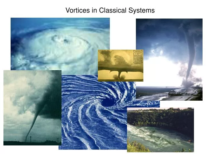
Vortices in Classical Systems. hc. e*. F = B · da = n. Vortices in Superconductors. wavefunction. Y = |Y| e i f. vortices in type II superconductors. supercurrent. |Y| 2. x. l. B. Abrikosov lattice. magnetic vector potential. Phase gradient.

E N D
hc e* F= B·da = n Vortices in Superconductors wavefunction Y = |Y|eif vortices in type II superconductors supercurrent |Y|2 x l B Abrikosov lattice magnetic vector potential Phase gradient magnetic flux quantization if Js = 0 Superconducting flux quantum e*=2e F0 = 20.7 Gauss-mm2
Vortices in Nb Film Cooled to 5.3K in 100G Df=2.01Hz 1mm Nanoscale Characterization of Single Vortex Motion Vancouver, May 12, 2005 Stanford O. Ausleander J.E. Hoffman N. Koshnick E.W.J. Straver E. Yenilmez McMaster R.A. Hughes J. Preston IBM D. Rugar Stanford University
Experimental Goal quantitative description of dynamics of a single vortex Aside 1: Two Possible Meanings for “Quantum Vortex” • a vortex in a superfluid • a vortex whose macroscopic degrees of freedom can be shown to obey quantum mechanics Aside 2: Vortices aren’t this simple: |Y|2 x l B
complex structure stuff conducting CuO planes Cuprate Superconductors c-axis Lawrence-Doniach model surface c-axis pancake vortex interlayer Josephson vortex vortex core John Clem
Vortex Interactions and Pinning Images from CUNY web site
5 1 0 4 1 0 Hc2 depinning 3 1 0 liquid / gas disordered 2 1 0 second magnetization peak B [G] first-order transition 1 1 0 0 2 0 4 0 6 0 8 0 1 0 0 quasi-ordered-lattice (Bragg glass) T [K] Vortex Matter in High-Tc Superconductors • layered structure, disorder, and high-T combine to give a rich phase diagram • model system for phase transitions • determines the critical current phase diagram in Bi2Sr2CaCu2O8 Zeldov & co-workers Nature 2001 Nelson and Seung 1989
Previous Single-Vortex Manipulation with Transport Current Finnemore and coworkers ongoing work (1988-present) Cabrera and coworkers 1992
z B r ab c SC ab plane What a vortex looks like to a surface magnetic probe: London model of the field from a vortex above a bulk superconductor: where = ab, r = (x, y), k = (kx , ky) For r2+z2» 2, a vortex looks like a monopole one penetration depth (ab)below the surface
Single-Vortex Manipulation with a micro-SQUID Create and observe vortex-antivortex pair: shielded leads Current applied to field coil pulls/pushes vortex with ~0.5pN Gardner et al. 2001, 2002
-3 10 -4 10 -5 10 -6 10 -7 10 -2 -1 0 1 2 10 10 10 10 10 F0=20.7Gm2 Magnetic Sensors for sub-Flux-Quantum Imagingrepresentative 4 Kelvin data from the literature and from the Moler Lab -1 10 MFM SQUIDs Hall Probes -2 10 ) Hess APL 1992 1/2 /Hz Hasselbach RSI 2001 (0.5 K) 0 2004 F 1000mB/Hz1/2 Bending APL 2001 2003 Chen Phys C 2002 2004 Flux Sensitivity( 2002 Bending APL 1996 10mB/Hz1/2 Moler RSI 2001 Kirtley APL 1995 2003 2004 m Sensor Size ( m)
Previous Single-Vortex Manipulation with Magnetic Force Microscopy
Magnetic Force Microscopy • Disadvantages of MFM: • Imperfect knowledge of tip geometry • Signal-to-noise • Advantages of MFM: • Signal-to-noise can be good enough • Good spatial resolution • Tip exerts force on vortex => • manipulation capability • Simultaneous topography possible Force between tip and sample: Image cantilever resonant frequency Df0 = dFz/dz better signal-to-noise
Vortices in Nb film field cooled to 5.3K in 100G external field 300 nm thick Onset Tc = 8.9K Midpoint Tc = 8.6K DTc = 0.57K 1mm
100 nm Next generation:Improved spatial resolution and interpretabilitywith metal-coated carbon nanotube tips cantilever with carbon nanotube tip typical metal-coated carbon nanotube tips 1mm conventional tip image nanotube tip image Z. Deng et al., APL, Dec. 2004.
Students and Postdocs Eric Straver Nick Koshnick Ophir Ausleander Jenny Hoffman Not shown: summer student Andrew Whitehead
I cantilever V magnetic tip Mesoscopic magnetism toolbox Magnetic Force Microscopy SQUID Magnetometry & Susceptometry Hall Probe Microscopy • Measures ForF • Sensitivity: difficult to quote • Spatial resolution: <30 nm goal = 10nm • Broad field and temp range • Measures • Sensitivity: 1 m0/Hz1/2 • (~0.3 mG/Hz1/2) • Spatial resolution: 4 mm • (goal = 0.5 mm) • B<100 G and T<10 K • Measures • Sensitivity: ~1-50 mG/Hz1/2 • (flux HF: 10 m0/Hz1/2) • (flux DC: 1 m0/Hz1/2) • Spatial resolution: 0.5 mm • (goal = 30 nm) • Broad field and temp range