Download
1 / 29
300 likes | 543 Vues
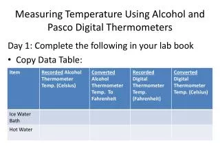
Temperature Measurements thermocouples, thermistors and resistance thermometers exposure and shielding of thermometers soil temperature measurements response times and sampling rates. Thermo couple measures temperature difference (T1 – T2) between two junctions. Copper. T1.

E N D
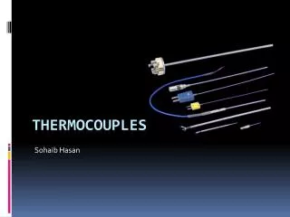
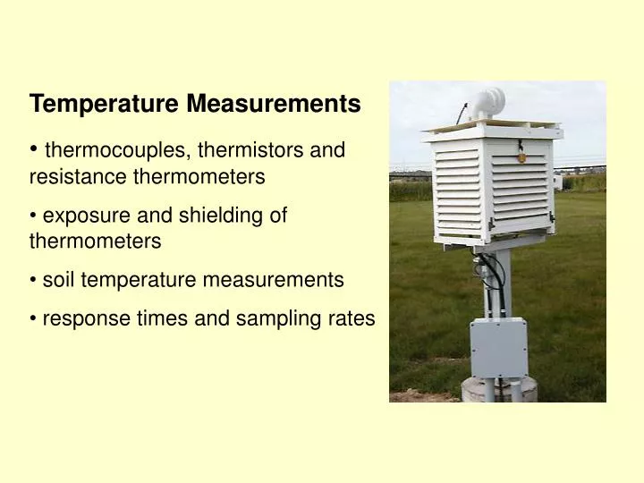
Temperature Measurements • thermocouples, thermistors and resistance thermometers • exposure and shielding of thermometers • soil temperature measurements • response times and sampling rates
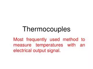
Thermocouple measures temperature difference (T1 – T2) between two junctions Copper T1 Constantan Voltage output T2 Copper • Easy to construct. Just twist together Copper and Constantan wires, and solder. • - Beautifully suited to measuring temperature differences directly. • Requires knowledge of temperature at T2 (“reference” temp) to get actual temperature at T1.
Can construct “thermopile” of several thermocouples connected in series. • Increases signal strength. Calibration factor increases according to the number of junction pairs in the “pile”. • Allows for spatial averaging, if desired. • For example, measuring soil temperature gradients… Voltage to Data Logger Soil surface Upper level Lower level = Cu, = Con
Data logger Copper Constantan Thermocouple measures temperature difference (T1 – T2) between two junctions Copper T1 Constantan Voltage output T2 Copper • Where is the second junction, when using logger? • What temperature difference is being measured?
The output signal from a thermocouple is not quite linear. Voltage change = (a + b T) (Temperature change) Microvolts per degree= 38.58 + 0.0428T for copper/constantan
Thermocouples • Estimate the maximum signal (in microvolts) you should expect from a thermocouple that is measuring an air temperature of 40 C. • Suppose you ignore the non-linearity of a thermocouple and always use the calibration factor for 0 C. What would the temperature error be at 40 C?
Thermocouples • Estimate the maximum signal (in microvolts) you should expect from a thermocouple that is measuring an air temperature of 40 C.Correct calibration factor is:38.58 + 0.0428 (40) = 40.29 microvolts/degree C • So signal is (40.29 microvolts/degree C) x 40 C = 1,611 microvolts or 1.611 millivolts • Suppose you ignore the non-linearity of a thermocouple and always use the calibration factor for 0 C. What would the temperature error be at 40 C? • Signal to be translated to temperature is 1,611 microvolts. Using calibration factor for 0C… 38.58 microvolts/C:1,611 microvolts /38.58 microvolts/C = 41.76 C. Answer is 1.76 C too high.
Electronic Temperature (and RH) probe which uses a thermistor, a semi-conductor material whose resistance changes with temperature. Advantages are… stronger signal change with temperature than thermocouple, and no reference needed.
Thermistor resistance decreases very non-linearly with increasing temperature. Suppose we take two resistance readings and average them. 250 Kohms50 KohmsAvg = 150 Kohms Average resistance gives correct average temperature? No!! Must convert to temperature before averaging. Thermistor-based probes can contain electronics to give a linear voltage output with temperature.
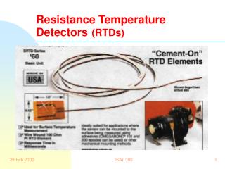
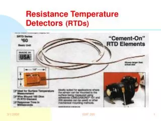
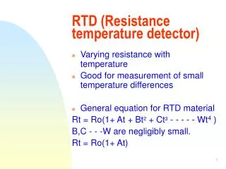
Platinum resistance-temperature detector • Resistance of wire changes with temperature • Platinum wire is typically used, wound inside a protective casing. - stable and almost linear resistance change with temp • - non-linearity can be accounted for in logger program, yielding very accurate temperature measurements that may be used to calibrate other temperature sensors. ~ 5 cm
Exposure of thermometers (Str – P. 41) Unshielded sensor will warm up during the day until heat loss to the air by convection matches the gain from radiation. (Tsensor – Tair) is the radiation error. Radiation error is reduced by:- Small sensor size- More air flow- Blocking the radiation Radiation gain Convection loss
Temperature probe will heat above air temperature if exposed to solar radiation. So….. what are features of a good thermometer shield? • shades the sensor • allows wind (or artificial ventilation) • doesn’t warm incoming air (high solar reflectivity) • avoids long wave gain from inside surface of shield to sensor (low emission efficiency of shield, poor conductor so inner temperature of shield not higher than air temperature) • avoids heat conduction down signal wires
Cut-away view Good features? Possible improvements? Here’s a shield that is often used at weather stations (the Gill shield).- a stack of upside-down plastic saucers .
Temp/RH probe, or thermocouple, can be used in “stacked saucers” shield.
Max and min thermometers T & RH probe The “Stevenson Screen” thermometer shield World-wide way of housing manually-read thermometers, and automated T and RH sensors
Good and poor features of the “Stevenson Screen” thermometer shield? • louvered for air flow- white, & double roof, for solar protection- wood for poor heat conduction- world-wide “standard” • needs regular repainting- bulky - too warm on calm, sunny days if no supplementary ventilation
Soil temperatures on an ideal sunny day.- temperature range decreases with depth,and max/min temperatures lag with depth. • Sensors must be waterproof • Sensor in a metal tube can give some spatial averaging • Place horizontally to spatially average at one depth • Place at an angle to average over a layer
Signals, sampling and sensors Imagine we take a sample every second with our data logger, for 10 seconds. For which of the 5 signals will our sampling yield a good 10-second average? Sampling rate must be at least twice as fast as the period of the signal you wish to average.
Tc = 2 sec Tc = 6 sec How quickly does a sensor respond? A step change is applied to the sensor at time zero. Time constant is time required for sensor to reach 63% of the step change. 63% level
Guidelines for good sampling over time. 1. Sampling rate must be at least 2x as fast as the period of the signal you wish to average. 2. Time constant of sensor should be 4x faster than period of the signal you wish to detect. Sensor’s response speed controls the signal fluctuations it “sees”. Signal period 2x slower Sampling rate Sensor 2x faster
How could you modify the time constant of a temperature sensor? • A very small thermocouple could be used without radiation shielding. Any disadvantages of a very small sensor? • You decide to ask your data system to sample once each minute. What time constant should your sensor have, and what is the period of the fastest signal you can resolve? • Suppose you need to measure temperature fluctuations as fast as 10 cycles per second. What sensor time constant is required, and how often would you sample?
Infra-red Thermometer (IRT) IRT Looks at I-R radiation from object. Sensor assumes objectobeys the Stefan-Boltzmann law which links radiation emitted to object temperature: Radiation in W/m2= sTIRT4where s = 5.67 X 10⁻⁸ and T is in 0K (0K = 0C + 273.2) Senses radiation solves S-B equation TIRT signal
Infra-red Thermometer (IRT) But real objects are not “perfect” emitters so the S-B equation needs a reduction factor called the emissivity (e) , which ranges from 0 1 Radiation in W/m2= esTobject 4 If an object is not a perfect emitter (that is, e < 1), then it is also not a perfect absorber, so it will reflect some incoming radiation from the surroundings. The fraction reflected is 1-e . Therefore a real object will send out an emittedI-R stream and a reflected I-R stream. Reflected I-R I-R from surroundings Emitted I-R
Infra-red Thermometer (IRT) • IRT sees IR emissions from two sources when pointed at an object… Emission = e s Tobject 4 Reflection = (1-e) (I-R from surroundings) Total IR seen = e s Tobject 4 + (1-e) (I-R surroundings) But the IRT changes IR radiation seen into a temperature using the “perfect” S-B law, so…sTIRT4 = e s Tobject 4 + (1- e) (I-R surroundings) This means TIRT does not equal Tobject unless e = 1. Errors are usually small, since e > 0.95 for most objects. Shiny metals are a notable exception. Their typical e < 0.5, so T-measurement with an IRT can be seriously degraded by reflected I-R from surroundings.
Practice with the IRT equation. • Suppose an IRT pointed at the sand on a beach shows the surface temperature is 41.2 C. The sand has an emissivity of 0.97. The sky is emitting 412 W/m2. What is the error between the true sand temperature and the value from the IRT? (~ 0.6 C error) • 2. A piece of aluminum foil (e = 0.15) was careless left on the grass near the beach. The foil temperature is 34.2 C. What is the error between the foil temperature and the value from the IRT? (~ 13 C error)
Using thermocouples for spatial sampling. 2. Link in parallel- same signal size as 1 couple (resistors 20x longest t/c).